Table of Contents
Advertisement
Quick Links
Download this manual
See also:
Repair Manual
Operation
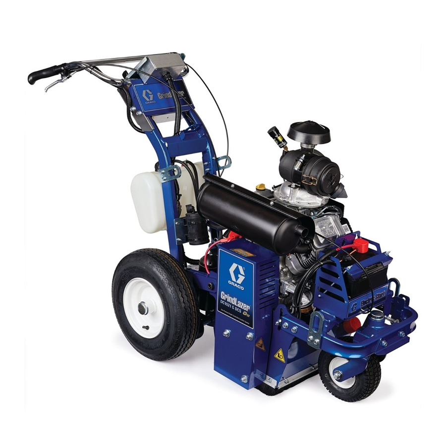
GrindLazer
For removal of materials from flat horizontal concrete and asphalt surfaces. For
professional use only.
Model 25M992 - Forward Cut
GrindLazer HP DC89 G (270 cc / 9 hp)
Model 25M993 - Forward Cut
GrindLazer HP DC1013 G (390 cc / 13 hp)
Model 25M994 - Reverse Up-Cut (Must be used with LineDriver™)
GrindLazer HP DC1021 G (627 cc / 21 hp Electric Start)
Model 25N658 - Forward Cut
GrindLazer HP DC1013 G DCS (390 cc / 13 hp Electric Start)
Model 25N659 - Reverse Up-Cut (Must be used with LineDriver™)
GrindLazer HP DC1021 G DCS (627 cc / 21 hp Electric Start)
IMPORTANT SAFETY INSTRUCTIONS
Read all warnings and instructions in this manual and in related manuals before using the equipment.
Be familiar with the controls and the proper usage of the equipment. Save all instructions.
25M992 / 25M993
™
25M994
(Drums, cutters, and LineDriver
www.graco.com/techsupport
LineDriver Operation - 312540
LineDriver ES Operation, Repair, Parts - 3A6623
25N658
™
sold separately)
3A5918B
EN
Related Manuals:
Repair - 3A5919
Parts - 3A5929
25N659
Advertisement
Table of Contents

Subscribe to Our Youtube Channel
Related Manuals for Graco GrindLazer 25M992


Summary of Contents for Graco GrindLazer 25M992
- Page 1 Read all warnings and instructions in this manual and in related manuals before using the equipment. Be familiar with the controls and the proper usage of the equipment. Save all instructions. 25M992 / 25M993 25N659 25M994 25N658 ™ (Drums, cutters, and LineDriver sold separately) www.graco.com/techsupport...
-
Page 2: Table Of Contents
Technical Data ......24 Graco Standard Warranty ....26... -
Page 3: Warnings
Warnings Warnings The following warnings are for the setup, use, grounding, maintenance, and repair of this equipment. The exclamation point symbol alerts you to a general warning and the hazard symbols refer to procedure-specific risks. When these symbols appear in the body of this manual or on warning labels, refer back to these Warnings. Product-specific hazard symbols and warnings not covered in this section may appear throughout the body of this manual where applicable. -
Page 4: Battery Disposal
Warnings WARNING FIRE AND EXPLOSION HAZARD Flammable fumes, such as solvent and paint fumes, in work area can ignite or explode. To help pre- vent fire and explosion: • Use equipment only in well ventilated area. • Do not fill fuel tank while engine is running or hot; shut off engine and let it cool. Fuel is flammable and can ignite or explode if spilled on hot surface. -
Page 5: Component Identification
Component Identification Component Identification 25M994 25M992 / 25M993 Component Description Engine Throttle Lever Adjusts engine speed. Power Switch Supplies power to Engine Engine Kill Button Clamps onto the operator and shuts engine off if cord is disconnected during oper- ation. Drum Adjustment Dial Sets depth of drum cut. -
Page 6: Component Identification (Dcs Models)
Component Identification (DCS Models) Component Identification (DCS Models) 25N659 25N658 Component Description Engine Throttle Lever Adjusts engine speed. Power Switch Supplies power to DCS Control and Engine. Engine Kill Button Clamps onto the operator and shuts engine off if cord is disconnected during operation. DCS Control Controls and displays depth of drum cut. -
Page 7: Setup
Setup Setup Models 25M992, 25M993 and 25N658 are designed to be operated by a single operator positioned at the back of the unit, or in conjunction with LineDriver. Models 25M994 and 25N659 can ONLY be operated with a To avoid unexpected startup, disconnect spark plug LineDriver. -
Page 8: Depth Control Wheels
Setup Depth Control Wheels 4. Once the proper drum height is achieved, slide the Drum Access Panel onto the hex shaft and door pin. Using Depth Control Wheels as a 5 in. or 10 in. Wide Cutting Guide To make a 5 in. cut, install two spacers (S) on outside of Depth Control Wheels (K). -
Page 9: Dust Control
Setup Dust Control 3. Loosen (but do not remove) three bolts (T) on Depth Control Wheel plate. Vacuum Attachment 1. If using a vacuum, attach vacuum hose to the Vacuum Port. ti15229a 4. Adjust plate until guide wheels lay flat on surface. 5. -
Page 10: Dcs Control (Dcs Models Only)
Setup DCS Control (DCS Models only) Buttons on the DCS Control have two functions, quick Zero Button press and long press. Quick press refers to pressing the Quick Press: Takes the drum to the surface. button and releasing the button quickly, while long press is pressing the button and holding the button for two or more seconds. - Page 11 Setup Cut Depth Button Up Arrow Button* Quick Press: Raises the drum by 0.01” (0.25mm, 10 Quick Press: Takes the drum to the Cut Depth Target. mil). Long Press: Raises the drum to Home position. Long Press: If at or above zero point: Opens new screen to select desired cut depth using up/down buttons.
- Page 12 Setup Menu Screens Menu Screen #3 - Model Select Your GrindLazer model name can be found on the han- To display the Menu Screens, hold down Home Button dlebar dashboard label. Select the model on the DCS from the Run Screen. To save menu settings and return Control which matches the model you have.
- Page 13 Setup Menu Screen #5 - Error Codes Error Codes E04: High Voltage Displays the most recent error code and the total num- E05: High Motor Current ber of times that error has occured. Cycle through previ- E08: Low Voltage ous error codes using Up/Down Buttons. E09: Hall Sensor Error E12: High Current (short circuit) E31: Home Button Error...
-
Page 14: Operation
Operation Operation 2. 25M994 & 25N659 Models Only: Attach LineDriver to GrindLazer. Do not start machine while drum is in contact with the ground. Doing so can cause the operator to lose control of the machine, resulting in property damage and/or personal injury. - Page 15 Operation 5. Non-DCS Models: Rotate Drum Adjustment Dial 7. Start Engine: counterclockwise until a hard stop is felt. a. Move fuel valve to open. ti5248a 25M992, 25M993 & 25N658 Models b. Move choke to closed. ti5249a 25M994 & 25N659 Models 25M992, 25M993 &...
-
Page 16: Cutting Material
Operation Cutting Material 5. Push down on handle bars, pull engagement lever, and lower drum into DOWN position slowly. NOTE: Dropping the drum to the down position quickly can cause damage to the drum and/or the DCS actua- tors. Maintain a safe operating distance from other people in the work area. -
Page 17: Cutting Drum Assemblies
Operation Diamond Blade Assembly DCS Models: On the DCS Control, press the Cut Depth Button to lower the drum to the programmed Watch Depth Control Wheels (K) during operation; if cut depth. See DCS Instructions, page 19, for more wheels are rotating, proper depth is being achieved. details. -
Page 18: Stop Cutting Material
Operation Stop Cutting Material Clean Up 1. Push down on handle bars until drum is locked into UP position. BURN HAZARD Avoid touching engine and drum after use until they have completely cooled. Clean the entire exterior of the machine after it has cooled at the end of each work day. -
Page 19: Dcs Instructions
Operation DCS Instructions Set Cut Depth Target: Quick press the Zero Button to take the drum to the Each time the DCS Control is turned on, the DCS actua- pavement surface. Set the Cut Depth Target by: tor will travel to the Home position. 1. - Page 20 Operation The DCS Control is now ready to grind/scarify. Long 3. Insert 6mm hex key into the port the screw plug was press down on the Handlebar Rocker Switch to lower the removed from. drum to your Cut Depth Target. Short press up or down One revolution of the hex key results in 1/8”...
-
Page 21: Maintenance
Maintenance Maintenance AS REQUIRED: • Check drive belt and tension and tighten or replace as needed. For additional information about engine Avoid touching engine and drum after use until they maintenance, see Honda (270 and 390 models) or have completely cooled. To avoid unexpected start Briggs and Stratton (480 models) engine manual. -
Page 22: Dcs Control Translations
DCS Control Translations DCS Control Translations English Español Français Deutsche International FINDING HOME ENCONTRANDO INICIO TROUVER LE DÉBUT START FINDEN HOME INICIO START DÉBUT DEPTH ALTURA TIEFE HAUTEUR TARGET OBJETIVO ZIEL OBJECTIF ZERO CERO NULL ZÉRO SEL MODEL MODELO MODELL MODELE LANGUAGE IDIOMA... - Page 23 DCS Control Translations English Español Français Deutsche International FREQUENCY FRECUENCIA ANZHAL FRÉQUENCE HIGH CURRENT ALTA CORRIENTE HOHER STROM COURANT ÉLEVÉ LOW VOLTAGE BAJO VOLTAJE NIEDERSPANNUNG BASSE TENSION HIGH VOLTAGE ALTO VOLTAJE HOCHSPANNUNG HAUTE TENSION HALL SENSORS SENSORES DE HALL HALL-SENSOREN CAPTEURS DE HALL HOME BUTTON BOTÓN DE INICIO...
-
Page 24: Technical Data
Technical Data Technical Data GrindLazer HP DC89 G (Model 25M992) Dimensions Unpackaged Packaged Height in./cm: 46 (116.8) 50.5 (128.3) Width in./cm: 28 (71.1) 37 (94.0) Length in.cm: 62 (157.5) 73 (185.4) Weight lb/kg: 300 (136) 400 (181) Noise (dBa) Sound Power per ISO 3744: 107.3 Sound Pressure measured at 3.1 feet (1m): 91.6... - Page 25 Technical Data GrindLazer HP DC1021 G (Model 25M994) Dimensions Unpackaged Packaged Height in./cm: 46 (116.8) 50.5 (128.3) Width in./cm: 28 (71.1) 37 (94.0) Length in.cm: 62 (157.5) 73 (185.4) Weight lb/kg: 365 (165) 465 (211) Noise (dBa) Sound Power per ISO 3744: 108.6 Sound Pressure measured at 3.1 feet (1m): 92.1...
-
Page 26: Graco Standard Warranty
With the exception of any special, extended, or limited warranty published by Graco, Graco will, for a period of twelve months from the date of sale, repair or replace any part of the equipment determined by Graco to be defective.
Need help?
Do you have a question about the GrindLazer 25M992 and is the answer not in the manual?
Questions and answers