Table of Contents
Advertisement
Quick Links
Repair
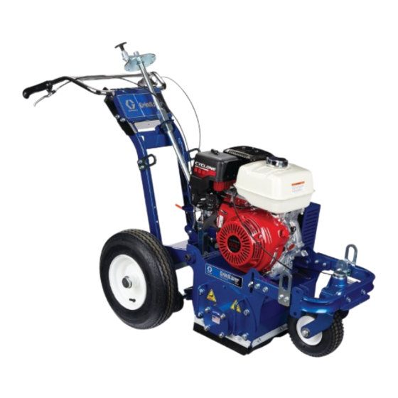
GrindLazer
For removal of materials from flat horizontal concrete and asphalt surfaces. For
professional use only.
Model 25M992 - Forward Cut
GrindLazer HP DC89 G (270 cc / 9 hp)
Model 25M993 - Forward Cut
GrindLazer HP DC1013 G (390 cc / 13 hp)
Model 25M994 - Reverse Up-Cut (Must be used with LineDriver™)
GrindLazer HP DC1021 G (627 cc / 21 hp Electric Start)
Model 25N658 - Forward Cut
GrindLazer HP DC1013 G DCS (390 cc / 13 hp Electric Start)
Model 25N659 - Reverse Up-Cut (Must be used with LineDriver™)
GrindLazer HP DC1021 G DCS (627 cc / 21 hp Electric Start)
IMPORTANT SAFETY INSTRUCTIONS
Read all warnings and instructions in this manual and in the Operation and Parts Manuals before using
the equipment. Be familiar with the controls and the proper usage of the equipment. Save all instructions.
25M992 / 25M993
™
25M994
(Drums, cutters, and LineDriver
www.graco.com/techsupport
LineDriver Operation - 312540
LineDriver ES Operation, Repair, Parts - 3A6623
25N658
™
sold separately)
3A5919C
EN
Related Manuals:
Repair - 3A5919
Parts - 3A5929
25N659
Advertisement
Table of Contents

Subscribe to Our Youtube Channel
Related Manuals for Graco GrindLazer HP DC89 G


Summary of Contents for Graco GrindLazer HP DC89 G
- Page 1 For removal of materials from flat horizontal concrete and asphalt surfaces. For professional use only. Model 25M992 - Forward Cut GrindLazer HP DC89 G (270 cc / 9 hp) Model 25M993 - Forward Cut GrindLazer HP DC1013 G (390 cc / 13 hp) Model 25M994 - Reverse Up-Cut (Must be used with LineDriver™)
-
Page 2: Table Of Contents
Technical Data ......25 Graco Standard Warranty ....27... -
Page 3: Warnings
Warnings Warnings The following warnings are for the setup, use, grounding, maintenance, and repair of this equipment. The exclamation point symbol alerts you to a general warning and the hazard symbols refer to procedure-specific risks. When these symbols appear in the body of this manual or on warning labels, refer back to these Warnings. Product-specific hazard symbols and warnings not covered in this section may appear throughout the body of this manual where applicable. -
Page 4: Battery Disposal
Warnings WARNING FIRE AND EXPLOSION HAZARD Flammable fumes, such as solvent and paint fumes, in work area can ignite or explode. To help pre- vent fire and explosion: • Use equipment only in well ventilated area. • Do not fill fuel tank while engine is running or hot; shut off engine and let it cool. Fuel is flammable and can ignite or explode if spilled on hot surface. -
Page 5: Component Identification
Component Identification Component Identification 25M994 25M992 / 25M993 Component Description Engine Throttle Lever Adjusts engine speed. Power Switch Supplies power to Engine Engine Kill Button Clamps onto the operator and shuts engine off if cord is disconnected during operation. Drum Adjustment Dial Sets depth of drum cut. -
Page 6: Component Identification (Dcs Models)
Component Identification (DCS Models) Component Identification (DCS Models) 25N659 25N658 Component Description Engine Throttle Lever Adjusts engine speed. Power Switch Supplies power to DCS Control and Engine. Engine Kill Button Clamps onto the operator and shuts engine off if cord is disconnected during operation. DCS Control Controls and displays depth of drum cut. -
Page 7: Drum Replacement
Drum Replacement Drum Replacement 1. Slide replacement drum onto hex shaft. Avoid touching or handling drum after use until it has completely cooled. To avoid injury from unexpected start up, disconnect spark plug wire and black battery cable (electric start models only) before you service your unit. -
Page 8: Cutter Replacement
Avoid touching or handling drum after use until it has completely cooled. Different drum configurations can be used for different applications. Visit www.graco.com/drumassembly for instructions on how to assemble various drum configurations. Removal (Carbide Flail/Carbide Miller) 1. Remove drum (see Drum Replacement, page 7). - Page 9 Cutter Replacement Removal (Diamond Blades) Installation (Diamond Blades) 1. Remove drum (see Drum Replacement, page 7). 1. Replace all spacers and diamond blades in the sequence and orientation shown below (blades 2. Place drum in vise. should be rotated in alternating segments when stacking).
-
Page 10: Diamond Blades
Cutter Replacement Diamond Blades Number of Number of For best performance, use 1/4 in. spacers on each end of Groove Number Steel 1/8 in. Aluminum 1/4 shaft to center diamond blades on drum. Width of Blades Spacers in. Spacers 1 in. (2.5 cm) 1/4 in. -
Page 11: Belt Replacement
Belt Replacement Belt Replacement 4. Tighten bottom bolt to lower pulley plate. To avoid injury from unexpected start up, disconnect spark plug wire and black battery cable (electric start models only) before you service your unit. Removal 1. Remove three nuts and washers. Remove belt shroud. - Page 12 Belt Replacement Installation 1. Install new belt. Belt Tension Recommendations: 3VX355 Belt DC89 DC1013 DC1021 Tension (Lbf) 145 +/- 5 193 +/- 7 194 +/- 7 Belt Frequency (Hz) 91 +/- 2 105 +/- 2 105 +/- 2 Used Tension (Lbf) 125 +/- 5 167 +/- 7 167 +/- 7...
-
Page 13: Clutch Replacement
Clutch Replacement Clutch Replacement Installation 1. Install clutch. To avoid injury from unexpected start up, disconnect spark plug wire and black battery cable (electric start models only) before you service your unit. Removal 1. Remove belt guard and belt (see Belt Replacement, page 11). -
Page 14: Pulley Replacement
Pulley Replacement Pulley Replacement Installation 6. Install pulley onto hex shaft. To avoid injury from unexpected start up, disconnect spark plug wire and black battery cable (electric start models only) before you service your unit. Removal 1. Remove drum (see Drum Replacement, page 7). 2. -
Page 15: Brush Replacement
Brush Replacement Brush Replacement Installation 1. Install new brush. To avoid injury from unexpected start up, disconnect spark plug wire and black battery cable (electric start models only) before you service your unit. Removal 1. Remove two mounting bolts. ti15078b 2. -
Page 16: Drive Bearing Assembly Replacement
Drive Bearing Assembly Replacement Drive Bearing Assembly Replacement To avoid injury from unexpected start up, disconnect spark plug wire and black battery cable (electric start models only) before you service your unit. Door Bearing Assembly ti17815a Removal 4. Tighten four nuts on bearing assembly to secure it into place. -
Page 17: Drive Bearing Assembly Removal
Drive Bearing Assembly Replacement Drive Bearing Assembly c. Remove sheave. Removal 1. Remove door from unit and remove any cutting drum on machine. ti14767b ti15126a d. Remove set screw from bushing. ti14765a 2. Remove belt guard and belt (see page 10). 3. -
Page 18: Drive Bearing Assembly Installation
Drive Bearing Assembly Replacement 5. Slide shaft assembly out of holes. 3. Make sure drive shaft key is assembled as shown below. ti15125b ti17820a Sheave Installation Drive Bearing Assembly Installation 1. Insert bushing onto drive shaft. Make sure key is in place. -
Page 19: Troubleshooting
Troubleshooting Troubleshooting To avoid injury from unexpected start up, disconnect spark plug wire and black battery cable (electric start models only) before you service your unit. Problem Cause Solution Engine will not start Engine switch is OFF. Turn engine switch ON. Engine is out of gas. -
Page 20: Dcs Models Only
Troubleshooting DCS Models only Problem Cause Solution DCS Control not turning on Blown fuse on DCS Power wire. Replace fuse on DCS Power wire. Power Switch is OFF or damaged. Turn Power Switch ON. Replace Power Switch if damged. Battery is dead. Charge Battery. -
Page 21: Dcs Error Codes
Troubleshooting DCS Error Codes To clear an error code on the DCS Control: 1. Turn DCS Power Switch to OFF. 2. Address/Fix the issue. 3. Turn DCS Power Switch to ON. Error Cause Solution E04: High Voltage (20VDC or Battery is damaged. Replace battery. -
Page 22: Dcs Actuator Rod Does Not Move
Troubleshooting DCS Actuator Rod Does Not Move Use this flow chart if the DCS Actuator Rod does not move or if the DCS displays error code E09 (Hall Sensor Error). Reference Wiring Diagram, page 23. Turn power switch to OFF. Remove the blue shroud behind the DCS Control. Ensure you have a good 12V battery installed. -
Page 23: Wiring Diagram
Wiring Diagram Wiring Diagram DCS System 3A5919C... -
Page 24: Dcs Control Box
Wiring Diagram DCS Control Box Powers Display 3A5919C... -
Page 25: Technical Data
Technical Data Technical Data GrindLazer HP DC89 G (Model 25M992) Dimensions Unpackaged Packaged Height in./cm: 46 (116.8) 50.5 (128.3) Width in./cm: 28 (71.1) 37 (94.0) Length in.cm: 62 (157.5) 73 (185.4) Weight lb/kg: 300 (136) 400 (181) Noise (dBa) Sound Power per ISO 3744: 107.3... - Page 26 Technical Data GrindLazer HP DC1021 G (Model 25M994) Dimensions Unpackaged Packaged Height in./cm: 46 (116.8) 50.5 (128.3) Width in./cm: 28 (71.1) 37 (94.0) Length in.cm: 62 (157.5) 73 (185.4) Weight lb/kg: 365 (165) 465 (211) Noise (dBa) Sound Power per ISO 3744: 108.6 Sound Pressure measured at 3.1 feet (1m): 92.1...
-
Page 27: Graco Standard Warranty
With the exception of any special, extended, or limited warranty published by Graco, Graco will, for a period of twelve months from the date of sale, repair or replace any part of the equipment determined by Graco to be defective. -
Page 28: Graco Information
For patent information, see www.graco.com/patents. TO PLACE AN ORDER, contact your Graco distributor or call 1-800-690-2894 to identify the nearest distributor. All written and visual data contained in this document reflects the latest product information available at the time of publication.
Need help?
Do you have a question about the GrindLazer HP DC89 G and is the answer not in the manual?
Questions and answers