Table of Contents
Advertisement
Operation, Repair, Parts
™
GrindLazer
3A5578C
EN
For removal of materials from flat horizontal concrete and asphalt surfaces. For
professional use only.
Standard Series - Forward Cut
Model 25M842 - GrindLazer Standard DC87 G (200 cc / 6.5hp)
Model 25M843 - GrindLazer Standard DC89 G (270 cc / 9hp)
Pro Series - Forward Cut
Model 25M846 - GrindLazer Pro DC1013 G (390 cc / 13hp)
Model 25N667 - GrindLazer Pro DC89 G (270 cc / 9hp)
Model 25N668 - GrindLazer Pro DC1013 DCS (390 cc / 13hp Electric Start)
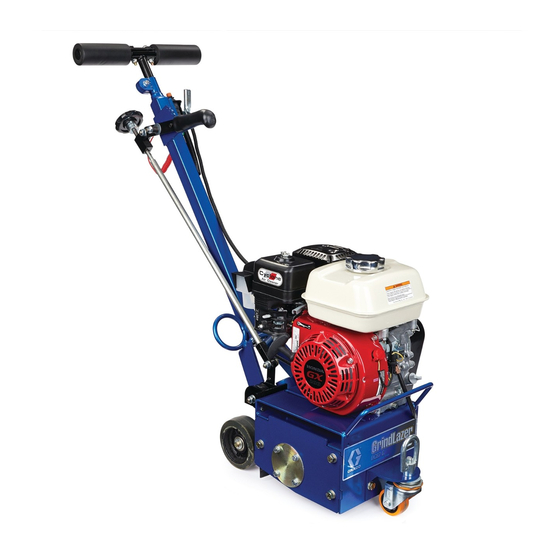
GrindLazer Standard Series
GrindLazer Pro Series
www.graco.com/techsupport
Advertisement
Table of Contents

Related Manuals for Graco GrindLazer 25M843


Summary of Contents for Graco GrindLazer 25M843
- Page 1 Model 25M846 - GrindLazer Pro DC1013 G (390 cc / 13hp) Model 25N667 - GrindLazer Pro DC89 G (270 cc / 9hp) Model 25N668 - GrindLazer Pro DC1013 DCS (390 cc / 13hp Electric Start) GrindLazer Standard Series GrindLazer Pro Series www.graco.com/techsupport...
-
Page 2: Table Of Contents
Graco Standard Warranty ........ -
Page 3: Warnings
Warnings Warnings The following warnings are for the setup, use, grounding, maintenance, and repair of this equipment. The exclamation point symbol alerts you to a general warning and the hazard symbols refer to procedure-specific risks. When these symbols appear in the body of this manual or on warning labels, refer back to these Warnings. Product-specific hazard symbols and warnings not covered in this section may appear throughout the body of this manual where applicable. - Page 4 Warnings WARNING FIRE AND EXPLOSION HAZARD Flammable fumes, such as solvent and paint fumes, in work area can ignite or explode. To help pre- vent fire and explosion: • Use equipment only in well ventilated area. • Do not fill fuel tank while engine is running or hot; shut off engine and let it cool. Fuel is flammable and can ignite or explode if spilled on hot surface.
-
Page 5: Component Identification
Component Identification Component Identification GrindLazer Standard Series Models Component Handlebar Depth Engage Lever (coarse adjustment) Locking Nut (for handle height adjustment) Drum Adjustment Dial (fine adjustments) Fixed Front Wheel (optional) Drum Access Panel Feathering Front Wheel Dust Skirt Vacuum Port Engine Engine Power Switch Engine Throttle... -
Page 6: Grindlazer Pro Series Models
Component Identification GrindLazer Pro Series Models Component Handlebar Drum Engage Lever Handlebar Adjustment Bolts Drum Adjustment Dial Drum Access Panel Dust Skirt Vacuum Port Engine Engine Power Switch Engine Throttle Engine Kill Button 3A5578C... -
Page 7: Grindlazer Pro Series Dcs Models
Component Identification GrindLazer Pro Series DCS Models Component Component Engine Kill Button Handlebar Pressure Indicator Power Switch Wheel Stop Handlebar Adjustment Bolts Hour Meter/Tachometer DCS Control Home Button Pressure Control Dial Zero Button Dust Skirt Cut Depth Button Vacuum Port Up/Down Buttons Engine Manual Height Adjustment... -
Page 8: Setup
Setup Setup Handle Bar Adjustment (Pro stopped by pressing down on the Engine Kill Button. Models Only) The handlebars are equipped with a high-density vibration suppression material to reduce operator fatigue when operating equipment. To adjust the handlebars to a new position for different height operators please follow these steps: 1. -
Page 9: Drum Installation/Replacement For Grindlazer Pro Series Models
Setup Drum Installation/Replacement 2. Remove the three hex head cap screws from the Drum Access Panel using the 17mm socket or for GrindLazer Pro Series wrench. Models 3. Remove Drum Access Panel (this may require the rubber mallet to break it loose). Normal use will require periodic drum inspection and may necessitate drum replacement. -
Page 10: Vacuum Attachment
Setup Vacuum Attachment 4. Slide out drum assembly (use caution as it is heavy). 1. If using a vacuum, attach vacuum hose to the Vacuum Port. 5. Once the cutter drum is removed take to a workbench for assembly. 2. Attach vacuum hose to the Inlet Port on the Cyclone Separator (optional) or vacuum. -
Page 11: Dcs Control (Dcs Models Only)
Setup DCS Control (DCS Models only) Buttons on the DCS Control have two functions, quick Zero Button press and long press. Quick press refers to pressing the Quick Press: Takes the drum to the surface. button and releasing the button quickly, while long press is pressing the button and holding the button for two or more seconds. - Page 12 Setup Cut Depth Button Up Arrow Button* Quick Press: Raises the drum by 0.01” (0.25mm, 10 Quick Press: Takes the drum to the Cut Depth Target. mil). Long Press: Raises the drum to Home position. Long Press: If at or above zero point: Opens new screen to select desired cut depth using up/down buttons.
- Page 13 Setup Menu Screens Menu Screen #3 - Model Select Your GrindLazer model name can be found on the han- To display the Menu Screens, hold down Home Button dlebar dashboard label. Select the model on the DCS from the Run Screen. To save menu settings and return Control which matches the model you have.
- Page 14 Setup Menu Screen #5 - Error Codes Error Codes E04: High Voltage Displays the most recent error code and the total number of E05: High Motor Current times that error has occured. Cycle through previous error E08: Low Voltage codes using Up/Down Buttons. E09: Hall Sensor Error E12: High Current (short circuit) E31: Home Button Error...
-
Page 15: Operation
Operation Operation If the Engine Does Not Start • Check engine for proper gas level. • Check the spark plug. Make sure socket areas are clean and clear of debris, and the proper gap is set. Replace if needed. • Turn the Engine Power Switch on the front of the engine to “On”. -
Page 16: Cutting Material
Operation Cutting Material 4. Slide Engine Throttle to desired setting. Maintain a safe operating distance from other people in the work area. Avoid any pipes, columns, openings, or any other objects protruding from your work sur- face. Before substrate removal, test run the drum with cutters not touching the surface. -
Page 17: Cutting Drum Assemblies
1/32 in. (0.8 mm) to get to the desired depth. Different drum configurations can be used for different applications. Visit www.graco.com/drumassembly • Make certain that the drum is positioned to where instructions on how to assemble various drum only the cutter tips strike the surface, and that the configurations. -
Page 18: Stop Cutting Material
Operation Stop Cutting Material 3. Depress Engine Kill Button and turn Engine Power Switch to “OFF”. 1. Raise Drum Engage Lever so that the drum is off the ground. 4. Clean the entire exterior of the machine after it has cooled. -
Page 19: Dcs Instructions
Operation Set Cut Depth Target: DCS Instructions Quick press the Zero Button to take the drum to the pavement surface. Set the Cut Depth Target by: Each time the DCS Control is turned on, the DCS actua- tor will travel to the Home position. 1. - Page 20 Operation The DCS Control is now ready to grind/scarify. Long 3. Insert 6mm hex key into the port the screw plug was press down on the Handlebar Rocker Switch to lower removed from. the drum to your Cut Depth Target. Short press up or One revolution of the hex key results in 1/8”...
-
Page 21: Maintenance
Maintenance Maintenance AFTER THE FIRST 20 HOURS OF OPERATION: • Drain engine oil and refill with clean oil. See engine Avoid touching engine and drum after use until they manual for correct viscosity. have completely cooled. To avoid unexpected start up, disconnect spark plug wire before you service EVERY 40-50 HOURS OF OPERATION: your unit. -
Page 22: Dcs Control Translations
DCS Control Translations DCS Control Translations English Español Français Deutsche International FINDING HOME ENCONTRANDO INICIO TROUVER LE DÉBUT START FINDEN HOME INICIO START DÉBUT DEPTH ALTURA TIEFE HAUTEUR TARGET OBJETIVO ZIEL OBJECTIF ZERO CERO NULL ZÉRO SEL MODEL MODELO MODELL MODELE LANGUAGE IDIOMA... - Page 23 DCS Control Translations English Español Français Deutsche International FREQUENCY FRECUENCIA ANZHAL FRÉQUENCE HIGH CURRENT ALTA CORRIENTE HOHER STROM COURANT ÉLEVÉ LOW VOLTAGE BAJO VOLTAJE NIEDERSPANNUNG BASSE TENSION HIGH VOLTAGE ALTO VOLTAJE HOCHSPANNUNG HAUTE TENSION HALL SENSORS SENSORES DE HALL HALL-SENSOREN CAPTEURS DE HALL HOME BUTTON BOTÓN DE INICIO...
-
Page 24: Repair
Repair Repair Drum Replacement for 4. Slide out drum assembly (use caution as it is heavy). GrindLazer Standard Series Models Normal use will require periodic drum inspection and may necessitate drum replacement. Time of replacement will vary according to usage and load factors. -
Page 25: Belt Replacement (Standard Models)
Repair c. Lube all metal contacts. 7. Align and slide drum back onto the hex shaft. To avoid injury from unexpected start up, disconnect 8. Replace Drum Access Panel (lift up and lock into spark plug wire before you service your unit. place) over hex shaft and secure hardware. - Page 26 Repair 4. Using the 1/2” socket or wrench, loosen (do not 8. Verify pulleys are properly aligned, tighten remove) the four nylock nuts locking down the everything down and re-check pulley alignment one engine until the engine slides freely. last time. 5.
-
Page 27: Belt Replacement (Pro Models)
Repair Belt Replacement (Pro Models) 5. Use a 9/16” wrench to loosen the jackscrew retaining nut. Normal wear may necessitate belt tensioning or 6. Using the 3/8” open-end wrench, begin to screw the replacement. Time of replacement will vary according to motor plate jackscrew back into the long hex nut usage and belt load factors. - Page 28 Repair 11. Using the straight edge, lay it across the lower 14. From the front of the machine, observe the motor pulley outer face and against the upper pulley. They plate to machine alignment. Tightening the belts must be directly over top of each other to ensure with the jackscrew tends to cause the right side of long belt life.
-
Page 29: Belt Alignment
Repair Bearing Replacement (Standard 17. Replace the belt cover using the 3/4” wrench. Models) Tools required: 1. 16mm socket or wrench 2. 1/2” socket or wrench 3. 9/16” socket or wrench 4. 13mm socket or wrench 5. Flat head screw driver 6. -
Page 30: Bearing Replacement (Pro Models)
Repair Bearing Replacement (Pro 3. Once the pulley is removed, the bearing assembly on that side can be removed using the 6mm hex Models) key. Tools required: 1. 7/16” socket or wrench 2. 1/2” socket or wrench 3. 1” open-end wrench 4. - Page 31 Repair 3. Pulley removal: 4. Slide the shaft out by removing the 2 set screws locking it in place using the 3/16” hex key. a. Remove the remaining 3 screws using the 7/16” socket and insert them by hand into the threaded holes as shown below (3B).
-
Page 32: Diamond (High Speed) Kit Installation (Pro Models Only)
Repair Diamond (High Speed) Kit Installation (Pro Models Only) 2. Set the engine pulley aside, and move the lower pulley to the engine’s shaft (the bushing required is part of the high speed kit). To avoid injury from unexpected start up, disconnect 3. -
Page 33: Troubleshooting
End plates or bushings worn Replace the end plates and/or bushings Shafts worn Replace the shafts Cutters shaft breakage unevenly/prematurely Wrong cutter set up www.graco.com/drumassembly Visit proper setup Over 40 hours service life Replace shafts and bushings Drum hitting ground Raise drum... -
Page 34: Dcs Models Only
Troubleshooting DCS Models only Problem Cause Solution DCS Control not turning Blown fuse on DCS Power wire. Replace fuse on DCS Power wire. Power Switch is OFF or damaged. Turn Power Switch ON. Replace Power Switch if damged. Battery is dead. Charge Battery. -
Page 35: Dcs Error Codes
Troubleshooting DCS Error Codes To clear an error code on the DCS Control: 1. Turn DCS Power Switch to OFF. 2. Address/Fix the issue. 3. Turn DCS Power Switch to ON. Error Cause Solution E04: High Voltage (20VDC or Battery is damaged. Replace battery. - Page 36 Troubleshooting Error Cause Solution E34: Up Button Error The Up Button or Handlebar Rocker Switch is stuck or shorted. Disconnect Handlebar Rocker Switch from the DCS Control. Clear the error code. If the error code reappears 30 seconds after turn- ing the Power Switch back ON, the problem is the Up Button on the DCS Control.
-
Page 37: Dcs Actuator Rod Does Not Move
Troubleshooting DCS Actuator Rod Does Not Move Use this flow chart if the DCS Actuator Rod does not move or if the DCS displays error code E09 (Hall Sensor Error). Reference Wiring Diagram, page 63. Turn power switch to OFF. Remove the blue shroud behind the DCS Control. Ensure you have a good 12V battery installed. -
Page 38: Parts
Parts Parts Drive Assembly (25M842) Ref. Torque 50-60 in-lb (5.6-6.8 N•m) 40-40 in-lb (4.5-5.0 N•m) 200-225 in-lb (22.5-25.5 N•m) *Use industry standard torques when not specified. 3A5578C... -
Page 39: Drive Assembly Parts List (25M842)
Parts Drive Assembly Parts List (25M842) Item: P/N Description 17W099 5/16-18 Nut 17W087 5/16” Flat Washer 17W288 6.5 HP Engine 17W291 5/16-18x1.5” Carriage Bolt 17W292 M5-1.0x12mm Set Screw 17W994 Engine Pulley 17W038 3/16” Key 17W995 Woodruff Key 17W996 Lower Pulley 17W997 Drive Belt 17W061... -
Page 40: Drive Assembly (25M843)
Parts Drive Assembly (25M843) Ref. Torque 50-60 in-lb (5.6-6.8 N•m) 40-40 in-lb (4.5-5.0 N•m) 200-225 in-lb (22.5-25.5 N•m) *Use industry standard torques when not specified. 3A5578C... -
Page 41: Drive Assembly Parts List (25M843)
Parts Drive Assembly Parts List (25M843) Item: P/N Description 17W095 3/8-16 Nut 17W008 3/8” Flat Washer 17W137 9 HP Engine 17W307 Engine Spacer 17W308 3/8-16x2” Carriage Bolt 17W292 M6-1.0x12mm Set Screw 17W306 Engine Pulley 17W088 1/4” Key 17W995 Woodruff Key 17W996 Lower Pulley 17W304... -
Page 42: Guide Bar Assembly (25M842 And 25M843)
Parts Guide Bar Assembly (25M842 and 25M843) Ref. Torque 100-110 in-lb (11.3-12.4 N•m) *Use industry standard torques when not specified. 3A5578C... -
Page 43: Guide Bar Assembly (25M842 And 25M843) Parts List
Parts Guide Bar Assembly (25M842 and 25M843) Parts List Item: P/N Description 17X006 Handlebar Assembly 17X007 Guide Bar 17X008 Wheel Carrier 17X009 Height Adjustment Rod 17X010 Lower Height Adjustment Clevis 17X011 Upper Height Adjustment Clevis 17X012 Height Adjustment Lever Assembly 17X013 M8-1.25x20mm Hex Cap Screw 17X014... -
Page 44: Primary Housing Assembly (25M842 And 25M843)
Parts Primary Housing Assembly (25M842 and 25M843) Ref. Torque 28-30 ft-lb (38-40 N•m) *Use industry standard torques when not specified. 3A5578C... -
Page 45: Primary Housing Assembly (25M842 And 25M843) Parts List
Parts Primary Housing Assembly (25M842 and 25M843) Parts List Item: P/N Description 17X036 Front Caster Wheel Assembly 17X019 M10-1.5x2.5mm Hex Cap Screw 17W425 M10 Flat Washer 17W424 M10-1.5 Nylon Nut 17X037 Dust Flap Retention Bar 17X038 Dust Flap 17X004 M10 Lock Washer 17X040 Belt Guard Bracket 17X033... -
Page 46: Drum Housing Assembly (25M842 And 25M843)
Parts Drum Housing Assembly (25M842 and 25M843) *Use industry standard torques when not specified. Drum Housing Assembly (25M842 and 25M843) Parts List 17X069 M8-1.25x18mm Hex Cap Screw Item: P/N Description 17X014 M8 Lock Washer 17X042 Main Housing 17X033 M8 Flat Washer 17X044 Side Plate 17X070... -
Page 47: Bearing And Shaft Assembly (25M846, 25N667 & 25N668)
Parts Bearing and Shaft Assembly (25M846, 25N667 & 25N668) Ref. Torque 30-32 ft-lb (40-43 N•m) *Use industry standard torques when not specified. Bearing and Shaft Assembly (25M846, 25N667 & 25N668) Parts List Item: P/N Description 17W026 Main frame 17W039 Drive shaft 17W038 Shaft key 17W046... -
Page 48: Rear Assembly (25M846 & 25N667)
Parts Rear Assembly (25M846 & 25N667) Ref. Torque 24-26 ft-lb (32.5-35.3 N•m) 180-200 in-lb (20.3-22.6 N•m) 70-75 in-lb (7.9-8.5 N•m) 160-170 in-lb (18.1-19.2 N•m) *Use industry standard torques when not specified. 3A5578C... -
Page 49: Rear Assembly (25M846 & 25N667) Parts List
17W049 Ball Knob 17W108 Cam Lever 17W285 Handlebar Back Plate 17W081 5/16-18x2.5” Hex Cap Screw 17W087 5/16” Flat Washer 17W099 5/16-18 Nylon Nut 17W084 #10-32x0.25” Set Screw 17W121 Damper Assembly 17W956 Linkage/Hand Wheel Assembly 17W138 Handle Graco (Model 25N667) 3A5578C... -
Page 50: Rear Assembly (25N668)
Parts Rear Assembly (25N668) 3A5578C... -
Page 51: Rear Assembly (25N668) Parts List
Parts Rear Assembly (25N668) Parts List Item: P/N Description 17W052 3/8-16x1” Hex Cap Screw 17W007 3/8” Lock Washer 17W008 3/8” Flat Washer 17W060 1/2-13x8” Hex Cap Screw 17W098 1/2” Flat Washer 17W062 1/2-13 Nylon Nut 17W057 1/2-20x4” Hex Cap Screw 17W955 1/2-20 Nylon Jam Nut 17W058... -
Page 52: Damper Assembly (25M846, 25N667)
Parts Damper Assembly (25M846, 25N667) Ref. Torque 150-160 in-lb (16.9-18.1 N•m) 95-105 in-lb (10.7-11.9 N•m) *Use industry standard torques when not specified. Damper Assembly (25M846 & 25N667) Parts List Item: P/N Description 17W126 Shock Absorber 17W123 Lower Attachment Link 17W122 Upper Attachment Link 17W124 5/16-18x1.75”... - Page 53 Parts NOTES 3A5578C...
-
Page 54: Front Assembly (25M846, 25N667 & 25N668)
Parts Front Assembly (25M846, 25N667 & 25N668) Ref. Torque 120-140 in-lb (13.6-15.8 N•m) 55-65 in-lb (6.2-7.3 N•m) 22-24 ft-lb (29.8-32.5 N•m) 19-21 ft-lb (25.8-28.5 N•m) Use industry standard torques when not specified. 3A5578C... -
Page 55: Front Assembly (25M846, 25N667 & 25N668) Parts List
Parts Front Assembly (25M846, 25N667 & 25N668) Parts List Item: P/N Description 17W030 Front Wheel (with bearings) 17W072 Locking Collar 17W032 Axle Shaft 17W023 1/4-20x1” Hex Cap Screw 17W020 1/4” Flat Washer 17W021 1/4” Fender Washer 17W022 1/4-20 Nylock Nut 17W019 Brush Strip Assembly (set of 4) 17W104... -
Page 56: Handle Bar Assembly (25M846)
Parts Handle Bar Assembly (25M846) Ref. Torque 22-24 ft-lb (29.8-32.5 N•m) *Use industry standard torques when not specified. Handle Bar Assembly (25M846) Parts List Item: P/N Description 17W281 Long Handle Bar Grip (49” Long) 17W005 Handle Bar Tubing 17W002 Short Handle Bar Grip (4” Long) 17W003 Handle Bar Clamp 17W006... -
Page 57: Handle Bar Assembly (25N668)
Parts Handle Bar Assembly (25N668) Ref. Torque 240-264 in-lb (27.1-30.0 N•m) 72--84 in-lb (8.1-9.5 N•m) *Use industry standard torques when not specified. Handle Bar Assembly (25N668) Parts List 17W009 3/4” Plastic Tube Cap Item: P/N Description 17Y120 Control Switch Housing 18A350 Handle Bar Tubing 15K780... -
Page 58: Drive Assembly (25M846 & 25N667)
Parts Drive Assembly (25M846 & 25N667) Ref. Torque 160-170 in-lb (18.1-19.2 N•m) *Use industry standard torques when not specified. 3A5578C... -
Page 59: Drive Assembly (25M846 & 25N667) Parts List
Parts Drive Assembly (25M846 & 25N667) Parts List Item: P/N Description 17W286 13hp Engine (Model 25M846) 123966 9hp Engine (Model 25N667) 17W080 3/8-16x1.75” Carriage Bolt 17W008 3/8” Flat Washer 17W095 3/8-16 Nylock Nut 17W960 Throttle Cable Assembly 17W961 Kill Switch Assembly 17W029 Deflector for Honda Engine 17W088... -
Page 60: Drive Assembly (25N668)
Parts Drive Assembly (25N668) Ref. Torque 12-15 ft-lb (16.3-20.3 N•m) 2-3 ft-lb (2.7-4.1 N•m) *Use industry standard torques when not specified. 3A5578C... -
Page 61: Drive Assembly (25N668) Parts List
Parts Drive Assembly (25N668) Parts List Item: P/N Description 17Y714 13hp Engine (Model 25N668) 17W080 3/8-16x1.75” Carriage Bolt 17W008 3/8” Flat Washer 17W095 3/8-16 Nylock Nut 17W960 Throttle Cable Assembly 18A198 Kill Switch Assembly 17W034 Engine Pulley 17W088 Key for Engine Pulley 17W096 3/8-24x1”... -
Page 62: Dcs Control Box 18A790
DCS Control Box 18A790 DCS Control Box 18A790 25N668 only Parts List Ref. Part Description Qty. Ref. Part Description Qty. 18A693 KIT, home button, DCS 18A690 KIT, DCS Control Box, machined 18A694 KIT, zero button, DCS includes 300a - 300f 18A695 KIT, cut cutton, DCS 17Y686 LABEL, control, GrindLazer DCS 18A696 KIT, up button, DCS... -
Page 63: Wiring Diagram
Wiring Diagram Wiring Diagram DCS System 3A5578C... -
Page 64: Dcs Control Box
Wiring Diagram DCS Control Box Powers Display 3A5578C... -
Page 65: Technical Data
Technical Data Technical Data GrindLazer Standard DC87 G (25M842) Noise level (dBa) Sound power 107 dBa per ISO 3744 Sound pressure 92 dBa measured at 3.1 feet (1m) Vibration level* Right/Left Hand 11.4 m/sec * Vibration measured per ISO 5349 based on 8 hr daily exposure Dimensions/Weight (unpackaged) Metric Height... -
Page 66: California Proposition 65
Technical Data GrindLazer Pro DC89 G (25N667) Noise level (dBa) Sound power 109 dBa per ISO 3744 Sound pressure 94 dBa measured at 3.1 feet (1m) Vibration level* Right/Left Hand 13.5 m/sec * Vibration measured per ISO 5349 based on 8 hr daily exposure Dimensions/Weight (unpackaged) Metric Height (handle up) -
Page 67: Graco Standard Warranty
With the exception of any special, extended, or limited warranty published by Graco, Graco will, for a period of twelve months from the date of sale, repair or replace any part of the equipment determined by Graco to be defective. - Page 68 For patent information, see www.graco.com/patents. TO PLACE AN ORDER, contact your Graco distributor or call 1-800-690-2894 to identify the nearest distributor. All written and visual data contained in this document reflects the latest product information available at the time of publication.
Need help?
Do you have a question about the GrindLazer 25M843 and is the answer not in the manual?
Questions and answers