Table of Contents
Advertisement
Quick Links
Advertisement
Table of Contents

Related Manuals for ADLINK Technology NuDAQ ACL-8113A


Summary of Contents for ADLINK Technology NuDAQ ACL-8113A
- Page 1 ® NuDAQ ACL-8113A 12-bit 32 Channels Isolated Analog Input Card User’s Guide...
- Page 2 Trademarks NuDAQ is registered trademark of ADLINK Technology Inc., Other product names mentioned herein are used for identification purposes only and may be trademarks and/or registered trademarks of their respective...
-
Page 4: Table Of Contents
Table of Contents Chapter 1 Introduction ...............1 Features ................1 Applications ................. 2 Specifications ............... 2 Software Support ..............3 1.4.1 Programming Library..................3 1.4.2 LabView Driver....................3 Chapter 2 Installation ..............4 What You Have ..............4 Unpacking................4 ACL-8113A's Layout ............. 5 Jumper and DIP Switch Description........ - Page 5 Chapter 6 Calibration..............28 What do you need .............. 28 VR Assignment ..............28 Bipolar A/D Adjustment ............29 Uni-polar A/D Adjustment ............ 29 Product Warranty/Service ............30 ii • Table of Contents...
- Page 6 How to Use This Guide This manual is designed to help you use the ACL-8113A. The manual describes how to modify various settings on the ACL-8113A card to meet your requirements. It is divided into seven chapters: u Chapter 1, "Introduction," gives an overview of the product features, applications, and specifications.
-
Page 8: Chapter 1 Introduction
Introduction The ACL-8113A is a 12-bit 32-channel single-ended isolated A/D card with ISA interface. The ACL-8113A is an ideal cost effective solution for applications in industrial measurement and monitoring. The ACL-8113A is designed to meet high voltage isolation on each analog channel. -
Page 9: Applications
Applications l Measurement of transducer and sensor data l Multiple channel measurement l Waveform acquisition and measurement l Process monitor l Vibration and transient analysis l Signal isolation Specifications The ACL-8113A provides the following specifications: Analog Input (A/D) l Input Channel: 32 Isolated channels l Resolution: 12-bit l Input Range: 10V Range:... -
Page 10: Software Support
General Specifications l Connector: 37-pin D-type connector l Operating Temperature: 0° C ~ 55° C l Storage Temperature: -20° C ~ 80° C l Humidity: 5 ~ 95%, non-condensing l Power Consumption: +5 V @ 960 mA maximum l Dimension: 160mm(L) X 122mm(W) Software Support 1.4.1 Programming Library... -
Page 11: Chapter 2 Installation
Installation This chapter describes how to install the ACL-8113A. At first, the contents in the package and unpacking information that you should be careful are described. The jumpers and switches setting for the ACL-8113A's base address and input range selection are also specified. What You Have In addition to this User's Manual, the package includes the following items: l ACL-8113A 32-CH S.E. -
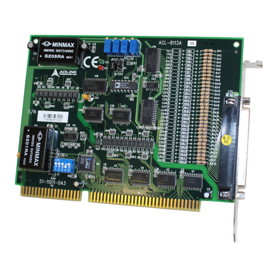
Page 12: Acl-8113A's Layout
Again inspect the module for damage. Press down on all the socketed IC's to make sure that they are properly seated. Do this only with the module place on a firm flat surface. Note: DO NOT APPLY POWER TO THE CARD IF IT HAS BEEN DAMAGED. You are now ready to install your ACL-8113A. -
Page 13: Jumper And Dip Switch Description
Jumper and DIP Switch Description You can change the ACL-8113A's channels and base address by setting jumpers and DIP switches on the card. The card's jumpers and switches are preset at the factory. Under normal circumstances, you should not need to change the jumper settings. -
Page 14: Input Range Selection
I/O port Address (hex) 000-00F 010-01F 210-21F (*) 220-22F 230-23F 3F0-3FF (*): default setting ON = 0; OFF = 1. A9, ..., A4 are corresponding to PC Bus address lines A3, A2, A1 and A0 are fixed by 0 with hardware How to define the base address for the ACL-8113A? The DIP1 to DIP6 in the switch SW1 are one to one corresponding to the PC bus address line A8 to A4. - Page 15 +10V (Default) +20V +10V +10V +10V +20V Input Range Setting +20V +20V Unipolar Bipolar (Default) Unipolar and Bipolar Setting Summary: AI Range & Modes Gain: Input Voltage Range X1: -5V ~ +5V Input Range 10V X2: -2.5V ~ +2.5V & X4: -1.25V ~ +1.25V Bipolar Mode X8: -0.625V ~ +0.625V...
-
Page 16: Connector Pin Assignment
Connector Pin Assignment The ACL-8113A comes equipped with one DB-37 female connector on the card's mounting brasket. The pin assignment of 37-pin female connector is illustrated in Figure 2.3 as following. AI10 AI11 AI12 AI13 AI14 AI15 A.GND A.GND A.GND A.GND AI16 AI17... -
Page 17: Chapter 3 Registers Format
Registers Format The detailed description of the register format and structure of the ACL- 8113A are specified in this chapter. This information is quite useful for the programmers who wish to handle the ACL-8113A card by low-level programming. In addition, the low level programming syntax is introduced. This information can help the beginners to operate the ACL-8113A in the shortest learning time. -
Page 18: A/D Data Registers
A/D Data Registers The ACL-8113A provides 32 single-ended A/D input channels , the converted digital data will store in the A/D data registers after the conversion. The 12 bits A/D data is put into two 8 bits registers. The low byte data (8 LSBs) are put in address BASE+4 and the high byte data (4 MSBs) are put in address BASE+5. -
Page 19: A/D Range Control Register
The combinations of CH4 ~ CH0 and their corresponding channel number is listed in the table 3.2 below. Channel No. Table 3.2 Channel Multiplexering A/D Range Control Register The A/D range register is used to adjust the analog input ranges for A/D channels. - Page 20 The possible gains and their corresponding input ranges are listed in the following table: Analog Input Range GAIN Input Range Setting by JP1 & ±5 V ±2.5 V 10V & ±1.25 V Bipolar ±0.625 V ±0.3125 V X 16 0 ~ +10 V 10V &...
-
Page 21: Chapter 4 Operation Theorem
Operation Theorem The operation theorem of the functions on ACL-8113A card is described in this chapter. The operation theorem can help you to understand how to manipulate or to program this card. Before programming the ACL-8113A to perform the A/D conversion, you should understand the following issues: l A/D conversion procedure l A/D signal source control... -
Page 22: A/D Signal Source Control
A/D Signal Source Control To control the A/D signal source, the signal type, signal channel and signal range should be considered. Signal Type The A/D signal sources of ACL-8113A could be single ended (SE) only. The single-ended mode has only one input relative to ground and it suitable for connecting with the floating signal source. -
Page 23: A/D Trigger Source Control
Signal Channel Control The value of AD channel Control register defines the channel to be selected. Signal Range The proper signal range is important for data acquisition. The input signal may be saturated if the A/D gain is too large. Sometimes, the resolution may be not enough if the signal is small. - Page 24 Define the base address of ACL-8113A card e.g. Base_addr = 0x220; et the desired input channel by MUX control register Base+ 10 2. S e.g. outportb( Base_addr + 10, 2); Trigger the A/D conversion by writing any data to Base+12 e.g.
- Page 25 The formula between the A/D data and the analog value is Direct Binary Coding: Bipolar ±10V: Voltage = (AD_Data * 20) / (4096 * gain) – (10 / gain) Bipolar ±5V: Voltage = (AD_Data * 10) / (4096 * gain) – (5 / gain) Uni-polar +10V: Voltage = (AD_Data * 10) / (4096 * gain) where the gain is 1,2,4,8,16...
-
Page 26: Chapter 5 C/C++ Library For Dos
C/C++ Library for DOS This chapter describes the DOS software library, which is free supplied. The DOS library software includes a utility program, C language library, and some demonstration programs, which can help you reduce the programming work. To program in Windows environment, please use ACLS-DLL2. The function reference manual of ACLS-DLL2 is included in the ADLINK CD. -
Page 27: Installation
Installation To install the DOS library software and utilities, please follow the following installation procedures: Put ADLINK CD into the appropriate CD-ROM drive. Type the following commands to change to the card’ s directory (X indicates the CD-ROM drive): X:\>CD \NuDAQISA\8113 Execute the setup batch program to install the software: X:\NuDAQISA\8113>SETUP C Language Library... -
Page 28: 8113_Initial
_8113_Initial Ø Description An ACL-8113A card is initialized according to the card number and the corresponding base address. Every ACL-8113A 32-channel A/D Card have to be initialized by this function before calling other functions. Ø Syntax int _8113_Initial(int card_number, int base_addresss ) Ø... -
Page 29: 8113_Actcard_Set
_8113_ActCard_Set Ø Description This function is used to switch active card which the A/D operations can be applied. After more than one cards are initialized by the function _8113_Initial, you have to use this function to select which card is activate currently. -
Page 30: 8113_Channel_Select/Deselect
_8113_Channel_Select/Deselect Ø Description The library functions that do the A/D conversions on multiple channels at once. You may select multiple channels to do the conversions on. The channels are not necessary to select as contiguous, i.e. the channels can be selected in any order, but the conversion sequence will be done in numerical order. -
Page 31: 8113_Gain_Select
printf( "AD channel 3 is now selected.\n" ); _8113_Channel_Select( 5); /* channel 5 is selected */ _8113_Channel_Select( 7); /* channel 7 is selected */ _8113_MAD_Acquire( ); /* The analog signals in channel 3, 5 and 7 will be converted to digital data and save in the Data8113[3], Data8113[5], and Data8113[7] */ _8113_Channel_Clear();... - Page 32 Ø Syntax int _8113_Gain_Select (int gain_code ) Ø Argument gain_code: the programmable gain of A/D conversion, the possible values are: AD_GAIN_1, AD_GAIN_2, AD_GAIN_4, and AD_GAIN_8. Ø Return Code ERR_NoRrror ERR_InvalidBoardNumber ERR_BaseAddressError Ø Example #include "8113.h" main() _8113_Initial( CARD_1, 0x220 ); /* Assume NoError when Initialize ACL-8113A */ _8113_Gain_Select( AD_GAIN_8 );...
-
Page 33: 8113_Ad_Acquire
_8113_AD_Acquire Ø Description: This function is used to poll the AD conversion data from a specified channel. It will trigger the AD conversion, and read the 12 bits A/D data until the data is ready ('data ready' bit is become to low). It is a special A/D conversion function, if you do not want to get converted data from the selected channels list. -
Page 34: 8113_Mad_Acquire
_8113_MAD_Acquire Ø Description This function does one A/D conversion on each of the selected channels, and puts the data in the array call ' Data_8113', which is defined in the file "8113.h". The data array is defined as: extern unsigned Data_8113[31]; If the channels in the selected list are 3, 8, 9, and 15, then the converted values for channel 3 will be stored in Data_8113[3], channel 8 in Data_8113[8], ..., etc. -
Page 35: Chapter 6 Calibration
Calibration In data acquisition process, how to calibrate your measurement devices to maintain its accuracy is very important. This chapter will guide you to calibrate your ACL-8113A to an accuracy condition. What do you need Before calibrating your ACL-8113A card, you should prepare some equipment for the calibration: 1. -
Page 36: Bipolar A/D Adjustment
Bipolar A/D Adjustment 1. Set jumper JP1 to "10V" and JP2 to "BI" position 2. Short the A.GND and AI0 ( Channel 0 analog input) 3. Trim VR3 until the reading of the A/D conversion data flickers between 2047 and 2048. 4. -
Page 37: Product Warranty/Service
Product Warranty/Service Seller warrants that equipment furnished will be free form defects in material and workmanship for a period of one year from the confirmed date of purchase of the original buyer and that upon written notice of any such defect, Seller will, at its option, repair or replace the defective item under the terms of this warranty, subject to the provisions and specific exclusions listed herein.
Need help?
Do you have a question about the NuDAQ ACL-8113A and is the answer not in the manual?
Questions and answers