Table of Contents
Advertisement
Quick Links
Advertisement
Table of Contents

Related Manuals for Extech Instruments HDV540


Summary of Contents for Extech Instruments HDV540
- Page 1 USER MANUAL High Definition VideoScope Model HDV500 ...
- Page 2 8.5 Video Recording, Viewing, and Deleting 8.6 Audio Voice‐Over with Video Recording 8.7 Image Capturing, Viewing, and Deleting 8.8 LED Work Lamp Intensity Control 8.9 System Reset Button 8.10 AV Connection to External Monitor 8.11 USB Connection for PC File Transfer and Battery Charging 9. FUNCTION PROGRAMMING MENU 10 9.1 Storage Devices (SD Cards and USB Flash Devices) 9.2 Set DATE/TIME and AUTO POWER OFF Time 9.3 AV Output Selections 9.4 Factory Default Reset and Firmware Version 9.5 Image and Video Files 10. MAINTENANCE 12 10.1 Cleaning 10.2 Battery Replacement 11. SPECIFICATIONS 13 12. WARRANTY 14 2 HDV540‐en‐US_V1.0 12/15...
-
Page 3: Introduction
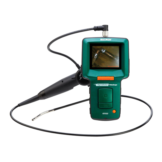
EXTECH INSTRUMENTS 1. Introduction Thank you for selecting this Extech High Definition VideoScope with articulating camera probe. This instrument is designed for use as a remote inspection device. It can be used to peer into tight spots and typically inaccessible places. This instrument can record, playback, store, and transfer video and images to a PC. Typical applications include HVAC installation and troubleshooting, cable routing, and automotive/maritime/aircraft inspection. This meter is shipped fully tested and, with proper use, will provide years of reliable service. Please visit our website (www.extech.com) to check for the latest version of this User Guide, Product Updates, Product Registration, and Customer Support. 1.1 Models and Descriptions HDV500 VideoScope (Main Unit Monitor only) HDV540 Kit: VideoScope with camera probe (HDV5‐6CAM‐1AFM) HDV5‐6CAM‐1AFM: Flexible macro camera probe, 1m cable, 6mm diameter 1.2 Features Image and video recording Image and video preview on LCD screen Glare‐free close‐up field of view Image and video storage to SD CARD or USB flash device Images and video transfer to a PC Adjustable LED intensity for camera NTSC and PAL output signal options (supplied AV cable) Digital zoom up to 4X for video and up to 10X for images Image rotation ... -
Page 4: Quick Start
Connect the camera to the screw hole (back of main unit) for mounting. Insert an SD Card into the slot (7) at the upper right side of main unit. Remove the protective decal from the main unit display. Press and hold the Power button (1) to power up. If the system does not start, please recharge the battery or use the supplied AC power adaptor. With the system powered, view the live camera image on the display. Zoom with the down arrow to 4X. Use caution when maneuvering and adjusting the camera probe and do not subject the camera probe to extreme bending positions. Use the Image (photo) button to take snapshots of the camera images and use the Video button to start and stop digital video recording. 10. To view stored images or videos, press the up arrow in the image or video mode. Use the arrow keys to scroll and use the OK button to open an image or video. Basic functions: Zoom stored Images: Press PHOTO button in the viewer mode Video Pause/Resume: Press OK button in video view mode Video Restart: Short press either arrow button in video view mode Video Search: Long press on up arrow [rewind] or down arrow [fast‐forward] Press ESC from the image or video viewer to return to the main display 11. Transfer images to a PC as described later in this manual using USB cable. 12. Configure and customize the system using the Functions Menu (press OK). 13. When finished, turn power off by holding the power button for 2 seconds and then pack the system in the supplied protective carry case. 14. Please read the entire user manual to learn about other useful and advanced features. 4 HDV540‐en‐US_V1.0 12/15... -
Page 5: Main Unit And Camera Descriptions
4. Main Unit and Camera Descriptions 4.1 Main Unit Description Power button Video Record button with sub‐functions Snapshot (photo) Image button Power adaptor jack Audio headset jack (for voice‐overs) AV Output jack (PAL or NTSC) SD Card slot Keyed Camera signal jack Monitor display 10. USB jack 11. Function buttons (seen next section) 12. Camera LED work lamps intensity adjust Note: Reset button & mounting hole on back of unit. 4.2 Camera Description LED work lamps (4) Camera with macro lens Mounting screw connects to back of main unit Camera position lock mechanism Articulating (240 ) control remotely points the camera lens Camera signal cable connects to top of main unit 5 HDV540‐en‐US_V1.0 12/15... -
Page 6: Button Descriptions
Press to switch to video standby mode and to start/stop video recording Increment a programming value Open the video trash utility from the video viewer 6. Common Display Icons This is a list of the most commonly displayed icons. Menu and other icons are presented in the user manual sections where they apply. The red video Icon is shown while video is being recorded; The yellow video icon is shown when in the standby video mode. The red camera Icon is shown when a snapshot image is taken; The yellow camera icon is shown when in the standby image mode. Battery charge level 1X…4X Camera zoom levels 00:00:00 Video recording elapsed timer 2015-12-14 Date (YYYY:MM:DD) 22:56:25 Clock time (HH:MM:SS) SD Card or USB Flash Drive successfully formatted Error signal indicating that images or videos were not saved to SD Card or USB Flash Drive (typically due to lack of free space on a storage device) SD Card locked. SD Card must be unlocked before it can be used Video Play and Pause icons Video fast‐forward and fast‐rewind 6 HDV540‐en‐US_V1.0 12/15... -
Page 7: Rechargeable Battery And Ac Power Adaptor
The Universal AC Power Adaptor can be used to recharge the battery as explained in the next section. 7.2 Universal AC Power Adaptor The system also includes a Universal AC Power Adaptor for powering the system and recharging the battery. The AC Power Adaptor jack (4) is located on the upper right side of the main unit under the protective flap. 8. Operation 8.1 Connecting and Powering the System Connect the camera’s signal cable to the keyed jack (8) at the top of the main unit and secure tightly with the nut. Mount the camera to the main unit using the mounting screw hole on the back of the main unit. Insert the SD CARD into the slot (7) on the upper right of the main unit. Use the proper insertion orientation and do not force the card. USB Flash Drives can be used as explained later in this manual. The supplied Li‐Polymer rechargeable 3.7V battery powers the system. Alternatively, use the supplied universal AC power adaptor to power the system. Press and hold the Power button (1) for 2 seconds to switch the meter ON. If the main unit does not power up, please charge the battery or use the supplied AC power adaptor. Check that camera and main unit are operational by viewing the displayed camera image. 8.2 Main Display The main display appears as shown. Camera image area Video recording elapsed timer Magnification level (zoom) Battery power status Mode icon (video or photo) Date and Time 7 HDV540‐en‐US_V1.0 12/15... -
Page 8: Camera Articulation Control
Press the Video button (2) to begin recording. The yellow video icon (upper right) turns red while recording and the elapsed timer (upper left) begins counting. Press the Video button again to stop recording; the red video icon will return to yellow and the elapsed timer will reset to zero. The hourglass icon is shown when a recording (.avi) is being saved to the SD CARD or Flash Drive. This error symbol appears if the storage device does not have enough free space. The Lock symbol will appear if the SD Card is locked. To unlock the SD Card, first turn the system OFF, remove the SD Card from the slot, and switch the SD Card tab position. To view videos, press the up arrow from the main display and a list of video recordings will appear. Use the arrows to highlight a video and press OK to view it. The features below are available when viewing a video: o Short press on either arrow button jumps back to the beginning o Long press on an arrow button fast‐forwards (up arrow) or fast‐rewinds (down) o Use OK button to Pause/Resume o Use the ESC button to return to the main display. o Video button opens the trash utility. Use arrows to highlight the check mark (delete video) or the ‘X’ (keep video): press OK to complete the function. 8.6 Audio Voice‐Over with Video Recording The video recording function of this device offers audio voice‐over recording. Connect a microphone headset to the headset jack (5) on the right side of the meter (under the protective flap). Audio recording begins automatically when video recording starts. 8 HDV540‐en‐US_V1.0 12/15... -
Page 9: Image Capturing, Viewing, And Deleting
If the operating system appears locked or frozen, press the recessed reset button on the back of the main unit, using a paper clip or small tool, to reset the system. 8.10 AV Connection to External Monitor This instrument includes an AV output port (6) on the upper right side of the main unit (under the protective flap). Connect the main unit to a monitor using the supplied RCA‐to‐ PHONO cable (PHONO end connects to the main unit and two RCA plugs connect to the jacks on the external monitor). The system will send AV signals to the monitor for remote viewing when connected. 8.11 USB Connection for PC File Transfer and Battery Charging Connect the system to a PC using the supplied USB cable, via the USB port (10) on the main unit (right side, under protective flap). A dialog box appears prompting the user to select DATA mode (PC transfer) or Battery Charging mode. Navigate to the upper block (Data mode) using the arrow buttons and then press OK to allow the transfer of files to and from the SD Card and the PC. The USB Connection LOGO displays on screen. Now the PC sees the main unit as any other external drive where files and folders can be dragged and dropped. Select the lower block for Battery Charging mode. The main instrument’s battery status icon will animate as charging is taking place. Please allow up to 5 hours for a complete charge. 9 HDV540‐en‐US_V1.0 12/15... -
Page 10: Function Programming Menu
3. AV output selection (PAL or NTSC) 4. Factory default reset and Firmware version 5. Stored Image/Video folders/files navigation 9.1 Storage Devices (SD Cards and USB Flash Devices) From the main menu, use the arrow buttons to scroll to the Storage Device icon and press OK to open it. There are three rows of selections in this menu. ROW 1 (top). Select a storage device (SD Card or USB Flash Drive) with the OK button*. Also view the remaining storage capacity of the selected device. This symbol on row 1 indicates that the system is using a USB Flash Drive. This symbol on row 1 indicates that the system is using the SD CARD. *The SD Card and the USB Flash Drive can be used at the same time but only one can be selected at a time; select the active one using the OK button while row 1 is highlighted. ROW 2. Formatting utility; use the OK button to format the selected device. This symbol on row 2 is for formatting the USB Flash storage device. This symbol on row 2 is for formatting the SD CARD. This symbol is shown on the screen during formatting and the symbol appears when formatting completed. Note: The duration of formatting depends on the memory size of the storage device. ROW 3. Return to main menu with OK button press RETURN symbol in row 3; Press the OK button to return to the main menu. 10 HDV540‐en‐US_V1.0 12/15... -
Page 11: Set Date/Time And Auto Power Off Time
will change the symbol color to red which disables the Auto Power Off utility. 9.3 AV Output Selections From the main menu, use the arrow buttons to scroll to the AV Output icon and press OK to open it. Connect the Phone plug end of the AV cable to the AV Output port (6) of the Main Unit and connect the RCA connectors to the external monitor, respectively. Use the arrow buttons to highlight the desired output signal type (PAL or NTSC) and press OK to begin sending the output signal to the remote monitor. The display will exit the programming mode and return to the main operating display. Use the ESC key to abort the output selection process, if desired, and return to the programming main menu. 9.4 Factory Default Reset and Firmware Version From the main menu, use the arrow buttons to scroll to the Factory Default icon and press OK to open it. There are three rows of options in this menu: Top row is the factory default reset icon (to revert to factory default settings: highlight this icon with the arrow buttons and activate with the OK button). The middle row is the abort function. Press OK with the RETURN symbol highlighted to return to the main function menu. The bottom row shows the firmware version number. 11 HDV540‐en‐US_V1.0 12/15... -
Page 12: Image And Video Files
Pause/Resume. Use the VIDEO button (2) to open the trash utility. Use an arrow button to highlight the check mark (delete) or the ‘X’ (keep video); press OK to complete the function. Tip: Enter the image or video review mode from the main operating display by pressing the up arrow button without having to access this function menu. Use the arrow buttons to scroll the folders and files and use the OK button to open an image or video. Restart, fast forward/rewind, trash, and pause/resume functions operate in the same way as described in this section. 10. Maintenance 10.1 Cleaning The system is supplied with a lens cloth and lens swabs for cleaning the camera lens. A damp cloth can be used to wipe the main unit and the camera snake. Do not use abrasives or solvents to clean any part of the system. 10.2 Battery Replacement The internal rechargeable battery is not user serviceable. Please contact Extech for replacement services. 12 HDV540‐en‐US_V1.0 12/15... -
Page 13: Specifications
Camera Field of View (FOV) Camera work lamps Four (LED) lamps with intensity control (dial on left of main unit) Camera work lamp output 3500 Lux @ 20mm (max.) Total weight of main unit 14.1 oz. (400g) with battery Dimensions of main unit 8.3 x 4.3 x 1.6 in. (21 x 11 x 4cm) Operating temperature Main unit: 32~122 F (0~50 C); Camera: ‐4~158 F (‐20~70 C) Storage temperature Main unit: 32~122 F (0~50 C); Camera: ‐4~158 F (‐20~70 C) Battery Rechargeable Li‐Polymer battery 3.7 (V); not user‐serviceable Universal AC Adaptor VAC 100~240V, 50~60Hz, 0.3A Max. Power adapter DC 5V, 2.5A, 12.5W Battery life and charge time 4 hour battery life; Charging time 5 hours @ 77 F (25 C) Power consumption 340mA / 5 V IP Rating IP67 (compact, high resolution water‐proof camera probe) 13 HDV540‐en‐US_V1.0 12/15... -
Page 14: Warranty
The warranty set forth above is inclusive and no other warranty, whether written or oral, is expressed or implied. Calibration, Repair, and Customer Care Services FLIR Systems, Inc. offers repair and calibration services for the Extech Instruments products we sell. NIST certification for most products is also provided. Call the Customer Service Department for information on calibration services available for this product. Annual calibrations should be performed to verify meter performance and accuracy. Technical support and general customer service is also provided, refer to the contact information provided below. Support Lines: U.S. (877) 439‐8324; International: +1 (603) 324‐7800 Technical Support: Option 3; E‐mail: support@extech.com Repair & Returns: Option 4; E‐mail: repair@extech.com Product specifications are subject to change without notice Please visit our website for the most up‐to‐date information www.extech.com FLIR Commercial Systems, Inc., 9 Townsend West, Nashua, NH 03063 USA ISO 9001 Certified Copyright © 2015 FLIR Systems, Inc. All rights reserved including the right of reproduction in whole or in part in any form www.extech.com 14 HDV540‐en‐US_V1.0 12/15... - Page 15 garantie, écrite ou orale, n’est exprimée ou implicite. Calibrage, réparation et services après‐vente FLIR Systems, Inc. offre des services de calibrage et de réparation pour les produits Extech Instruments que nous commercialisons. Nous fournissons également une certification NIST pour la plupart des produits. Contactez notre service client pour toute information sur les services de calibrage disponibles pour ce produit. Un calibrage doit être effectué chaque année pour vérifier les performances et la précision du mètre. Nous offrons également une assistance technique et un service à la clientèle. Veuillez vous reporter aux coordonnées fournies ci‐dessous. Lignes d’assistance: États‐Unis (877) 439‐8324; international: +1 (603) 324‐ 7800 Service d’assistance technique : Option 3 ; E‐mail : support@extech.com Réparations et retours : Option 4 ; E‐mail : repair@extech.com Les spécifications produit sont sujettes à modifications sans préavis. Pour les toutes dernières informations, veuillez visiter notre site Web. www.extech.com FLIR Commercial Systems, Inc., 9 Townsend West, Nashua, NH 03063 USA Certifié ISO 9001 Copyright © 2015 FLIR Systems, Inc. Tous droits réservés, y compris la reproduction partielle ou totale sous quelque forme que ce soit. www.extech.com 15 HDV540‐en‐US_V1.0 12/15...
- Page 16 Además se provee Soporte Técnico y servicios generales al cliente, consulte la información de contacto en seguida. Líneas de soporte: EE.UU. (877) 439‐8324; Internacional: +1 (603) 324‐ 7800 Soporte Técnico Opción 3; correo electrónico: support@extech.com Reparación / Devoluciones: Opción 4; correo electrónico: repair@extech.com Las especificaciones del producto están sujetas a cambios sin aviso Por favor visite nuestra página en Internet para la información más actualizada www.extech.com FLIR Commercial Systems, Inc., 9 Townsend West, Nashua, NH 03063 USA Certificado ISO 9001 Copyright © 2015 FLIR Systems, Inc. Reservados todos los derechos, incluyendo el derecho de reproducción total o parcial en cualquier medio www.extech.com 16 HDV540‐en‐US_V1.0 12/15...
Need help?
Do you have a question about the HDV540 and is the answer not in the manual?
Questions and answers