Table of Contents
Advertisement
Quick Links
Advertisement
Table of Contents

Related Manuals for Extech Instruments HDV700


Summary of Contents for Extech Instruments HDV700
- Page 1 User Manual HDV700 High Definition VideoScope Kit...
-
Page 2: Table Of Contents
VideoScope .............. 6 Touch-Screen ............7 Using an External Monitor..........9 Connecting the Probe ............10 Powering the HDV700 ............11 Power the Display Unit ..........11 Battery Overview ............11 Battery Status Indicators ..........11 Charging the Battery ..........11 Power Reset Button .......... - Page 3 Downloading Media to a PC ........23 PC Interface..............24 PC Interface Overview ..........24 Connecting to a PC ........... 24 Accessing the HDV700 Directory on the PC ....24 Firmware Updates ............. 25 10.1 Obtaining the Firmware Update File ......25 10.2...
-
Page 5: Introduction
Introduction 1.1 Overview Thank you for selecting the HDV700 High Definition VideoScope kit. The kit is a rugged, splash proof (IP54 display unit) and waterproof (IP67 probe) video inspection system that includes the VideoScope, a detachable camera probe, and accessories. -
Page 6: Available Probes
VideoScope Kit with Four-Way Articulation 6.0 mm × 1 m length probe HDV750 VideoScope Kit with Plumbing Spool and 28 mm × 30 m length probe Note: To order the VideoScope display unit only, use part number HDV700. 1.4 Available Probes Probe part number Description HDV7C-55–HD-1... -
Page 7: Safety
Safety CAUTION Please read all user instructions and safety guidelines before proceeding. If the equipment is used in a manner not specified by the manufacturer, the protection provided by the equipment may be impaired. The battery is not user-serviceable. DO NOT open the unit to replace the bat- tery or to perform maintenance. - Page 8 Safety CAUTION INCOMPATIBLE SUBSTANCES MAY DAMAGE THE PROBE See the probe user manual for a list of specified liquids into which the probe can be inserted. CAUTION The IP54 splash proof rating applies to the VideoScope display unit. The IP67 water proof rating applies to all available probes.
-
Page 9: Quick Start
3. Carefully connect the camera probe as detailed in Section 5. 4. Remove the protective lens cap from the camera probe. 5. Long press the HDV700 power button (top of unit, on right), the Extech logo will appear. 6. The camera image will then appear with touch-screen icons, battery status icon, and date/time (see Section 4). -
Page 10: Product Descriptions
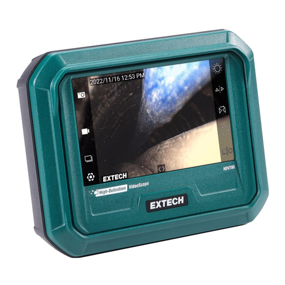
Product Descriptions Figure 4.1 VideoScope description. Front view on left, back view on left. 4.1 VideoScope 1. Touch-screen and camera monitor. 2. Power LED. Green when powered, red when charging. 3. Power button. Long press ON/OFF. 4. Reset button (recessed). Press to initialize the unit if it becomes unresponsive. -
Page 11: Touch-Screen
Product Descriptions 4.2 Touch-Screen When powered, the display appears as shown below. A description for each item is provided below. Figure 4.2 Touch-screen display. Items in ICON DESCRIPTION Figure 4.1 Tap to capture an image. Tap to start or stop a video recording. Tap to open the recorded image and video media gallery. - Page 12 Product Descriptions Tap to begin comparing stored images with the live camera feed on a split-screen. When you tap the icon, the image gallery opens. Select an image from the gallery to compare with the live image. The screen will split, showing the stored image and the live image side by side.
-
Page 13: Using An External Monitor
4.3 Using an External Monitor The micro HDMI port, inside the right side compartment, can be used to con- nect the HDV700 to an external monitor’s HDMI port. The external monitor will then show the camera images and other HDV700 display information. -
Page 14: Connecting The Probe
Connecting the Probe With the display unit powered OFF, connect a probe to the display unit as de- scribed below. The connection is made at the top of the display unit. The con- nector location is shown in Section 4. Each probe is supplied with its own user manual, please refer to the probe user manual for complete information. -
Page 15: Powering The Hdv700
Long press the power button to power ON or OFF. The power button is lo- cated on the top of the HDV700, on the right, as shown in Section 4. Check the battery status indicator, located on the upper right corner of the display, and charge the battery if necessary before using the instrument. -
Page 16: Power Reset Button
The button is recessed and requires a pin or similar tool to reach. When the reset button is pressed the HDV700 switches off. Power up the HDV700 to begin using the instrument. #NAS100121; r. AC/89755/89755; en-US... -
Page 17: Settings Menu
Settings Menu 7.1 Settings Menu Overview Figure 7.1 Settings Menu. The Settings menu allows you to quickly and easily customize the HDV700. Tap the Settings touch-screen icon to open the menu. The menu has two pages, tap the up/down arrow touch-screen icons to scroll. Tap a menu item to access it. -
Page 18: Image
Settings Menu 7.2.2 IMAGE Tap to open the Image Brightness and Contrast control menu. Figure 7.3 Image Settings Menu Tap and drag the sliders (2) as desired. Tap DEFAULT (3) to reset the image settings. Tap the left arrow (1) to return to the main menu. 7.2.3 SESSION In the Session menu you can create folders in which to organize images and video. -
Page 19: Tag
Settings Menu 5. Tap to delete a highlighted folder. Only folders that you have created can be deleted. 6. Scroll down to the next page (if any). 7. The top number shows the current page. The bottom number shows the total number of pages. -
Page 20: Usb Card Reader
There are no programmable settings to adjust in this menu. The menu text turns from grey to white, and the USB icon appears, when the HDV700 is connected to a PC. While connected, you can move images and video from the SD card to a PC and update the firmware. -
Page 21: Date / Time
(1) to return to the main menu. Do not use SD cards that were formatted on another device, as the filing sys- tems may differ. Always format SD cards with the HDV700 before use (the supplied card is formatted at the factory). -
Page 22: Language
Settings Menu to select the 12 or 24 hour clock. Tap the left arrow (1) to return to the main menu. 7.2.8 LANGUAGE Tap to open the Language menu. Figure 7.9 Language Settings Menu Tap the desired language (2). Tap the up/down arrow icons (3) to scroll pages. Tap the left arrow (1) to return to the main menu. -
Page 23: Regulatory
Settings Menu 7.2.11 REGULATORY Tap this item to view safety verifications, regulatory compliance certifications, and more. Figure 7.11 Regulatory information page. #NAS100121; r. AC/89755/89755; en-US... -
Page 24: Image And Video Recording
Image and Video Recording 8.1 Image and Video Basics The HDV700 allows you to capture still images (.jpg) and video (.mov). Tap the image capture touch-screen icon to save still images and tap the vid- eo record button to start/stop video recording. -
Page 25: Opened Images
10. Tap the arrow to exit the gallery. 8.3 Opened Images When you tap an image thumbnail, the image will open on the HDV700 dis- play. While the image is opened, you can type text onto the image, delete the image, and perform other actions as described in the call-out below. -
Page 26: Opened Videos
10. Return to the main thumbnail gallery. 8.4 Opened Videos When you tap a video thumbnail, the video will open on the HDV700 display. Tap the screen to stop/restart the video. You can perform other actions as de- scribed in the call-out below. -
Page 27: Recording Audio Over Video
USB port, located under the flap on the right side of the unit, and to a PC USB port. The HDV700 will be recognized by the PC as a new external storage drive. Simply drag files out of, and into (in the case of firmware upgrades), the HDV700 drive. -
Page 28: Pc Interface
PC USB-A port. Depending on the type of USB port on your PC, you may need to use a USB adaptor to connect correctly. Figure 9.1 Connect to a PC using the supplied USB-C (HDV700 port) to USB-A (PC port) cable. -
Page 29: Firmware Updates
Firmware Updates To update the firmware, carefully follow the steps in the following sections. The FLIR website is updated periodically to make improvements and so the screen examples, below, may not match the current format or configuration exactly. If you need assistance please contact FLIR support. 10.1 Obtaining the Firmware Update File 1. -
Page 30: Moving The Upgrade File To The Hdv700
10.4. NOTE Drag only the update file into the HDV700 root directory. Do not drag other files or folders that may accompany the update file (readme.txt, for example). Rename the existing firmware file before loading the new update file. This will allow you to revert to the earlier firmware version if necessary. -
Page 31: Executing The Firmware Update
Firmware Updates Figure 10.4 Windows PC example: Moving the update file to the HDV700 root directory. 10.3 Executing the Firmware Update 1. With the HDV700 disconnected from the PC, press the HDV700 Settings button to open the Settings menu. 2. Navigate to the INFO menu, tap INFO to open it, and then tap FIRMWARE UPGRADE;... -
Page 32: Specifications
Specifications Monitor 5 in. (12.7 cm) diagonal colour capacitive touch-screen dis- play (800 x 480) Stored images file JPEG format (1280 x 720) format Comments can be added directly onto images in the Media Gallery Stored video file format MP4 format (1280 x 720) Audio can be recorded over video Media storage capacity 32 G micro SD card (supplied);... - Page 33 Specifications Power supply Rechargeable lithium ion battery (4900 mAh) 3.5 hours charging and 6 hours operation at 79℉ (26℃) Do not charge the battery if the ambient temperature is > 104℉ (40℃) or < 32℉ (0℃) AC adaptor/charger (supplied) for US, UK, EU, and AUS plugs. Output is rated 100 to 240 VAC ±10%, 50/60 Hz.
-
Page 34: Limited 2-Year Warranty
Limited 2–Year Warranty FLIR Systems, Inc. warrants this Extech brand instrument to be free of defects in parts and workmanship for two (2) years from date of purchase. To view the full warranty please visit the site below. http://www.extech.com/support/warranties #NAS100121; r. AC/89755/89755; en-US... -
Page 35: Customer Support
CUSTOMER SUPPORT Customer Support Telephone List https://support.flir.com/contact Repair, Calibration, and Technical Support https://support.flir.com #NAS100121; r. AC/89755/89755; en-US... - Page 36 #NAS100121; r. AC/89755/89755; en-US...
- Page 38 User Manual last page Website http://www.flir.com Customer support http://support.flir.com Copyright © 2023, FLIR Systems, Inc. All rights reserved worldwide. Disclaimer Specifications subject to change without further notice. Models and accessories subject to regional market considerations. License procedures may apply. Products described herein may be subject to US Export Regulations.
Need help?
Do you have a question about the HDV700 and is the answer not in the manual?
Questions and answers