
Subscribe to Our Youtube Channel
Related Manuals for Extech Instruments CT70


Summary of Contents for Extech Instruments CT70
- Page 1 User Manual AC Circuit Load Tester Model CT70 GlobalTestSupply www. .com Find Quality Products Online at: sales@GlobalTestSupply.com...
-
Page 2: International Safety Symbols
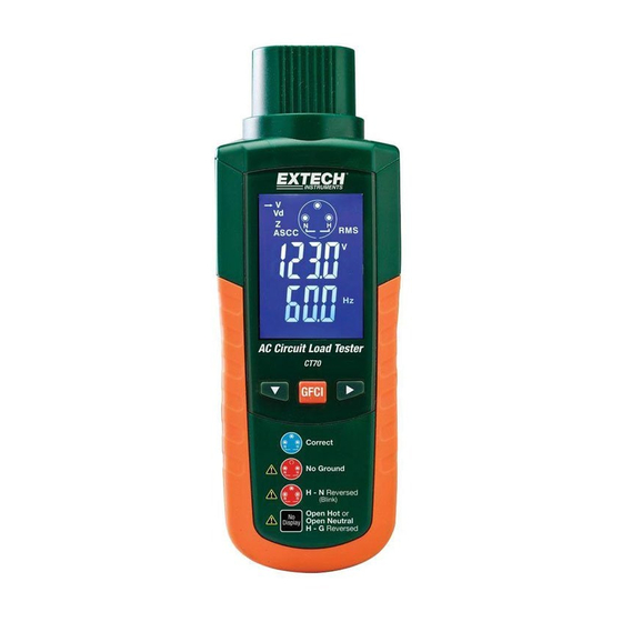
Introduction Congratulations on your purchase of the CT70 AC Circuit Load Tester. This device can detect circuit and wiring problems such as: Poor ground impedance, false grounds, missing ground fault protection, low voltage availability under load, and high ground-to-neutral voltage. In addition, the CT70 tests GFCI and EPD circuits. - Page 3 Ground to positive peak measurement Root Mean Square GFCI Ground Fault Equipment Protection Device test NEUT Neutral Overload m, M, k Unit of measure prefixes: milli, mega, and kilo CT70-en-GB_V8.5 2/19 GlobalTestSupply www. .com Find Quality Products Online at: sales@GlobalTestSupply.com...
-
Page 4: Operation Overview
Operation Overview The CT70 AC Circuit Load Tester can test outlets or circuits under load for proper wiring, reverse polarity, and the presence of a ground. The CT70 uses a simple menu-driven display to allow the user to quickly see line voltage, voltage drop under full load, ground-to-neutral voltage, and line impedance. - Page 5 To display the GFCI main menu window, press the GFCI button. To toggle the two tests use the button. Once the desired test is selected, press the GFCI button to start the test. These tests are further detailed below. CT70-en-GB_V8.5 2/19 GlobalTestSupply www.
-
Page 6: Testing Procedures
The wiring configuration is the first test result that is displayed. Refer to the table presented earlier in the user guide for the test result key. For wiring conditions other than normal, the CT70 is limited in the type of tests it can perform on a circuit and voltage drop tests can be made. - Page 7 Test 3: Voltage Drop Measurements To determine voltage drop, the CT70 measures line voltage, factors in the load, measures the loaded voltage, and then calculates the voltage drop. Results are provided for 120V circuits, with 12A, 15A, and 20A loads and 230V circuits with 5A, 8A, 10A loads.
- Page 8 Test 5: Impedance (Z) Measurements The impedance measurement capability of the CT70 is used to check Hot and Neutral impedance when voltage drop measurements are too high (greater than 5%). To determine where the problem is, measure the impedances and analyze the data as follows: If one impedance measurement is exceedingly higher than the other then the problem is with the conductor that shows the higher impedance.
- Page 9 The GFCI circuit should typically trip within 200ms because the power has been removed by the GFCI circuit). When the GFCI circuit is reset, the CT70 will display the elapsed time from start of test to power down. Press any button to return the meter to normal operation mode.
-
Page 10: Specifications
IEC1010-1 (2001): EN61010-1 (2001) Overvoltage Category II 300V Pollution Degree 2. Copyright © 2013-2019 FLIR Systems, Inc. All rights reserved including the right of reproduction in whole or in part in any form CT70-en-GB_V8.5 2/19 GlobalTestSupply www. .com Find Quality Products Online at: sales@GlobalTestSupply.com...
Need help?
Do you have a question about the CT70 and is the answer not in the manual?
Questions and answers