Table of Contents
Advertisement
MT-64E-002-J
Instruction Manual
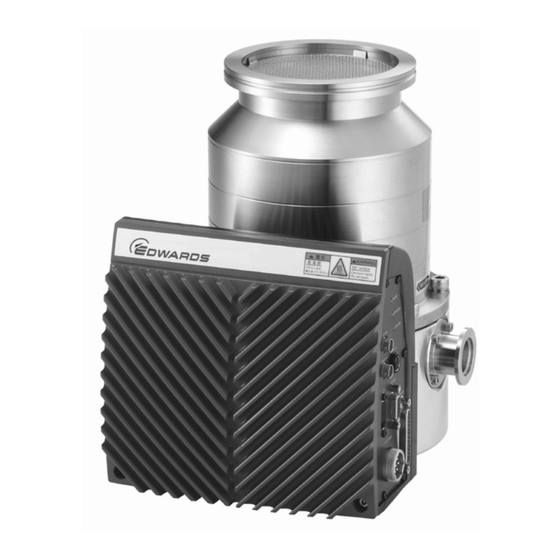
STP Series Turbomolecular Pumps
STP-iX455/iXL455 Series
Read through the Safety Precautions and
each section of this Manual carefully before
using the STP pump.
Keep this Manual in a place where you can
quickly access it at any time.
Copyright 2016 Edwards Japan Limited. All rights reserved. Printed in Japan.
Advertisement
Table of Contents
Troubleshooting

Related Manuals for Edwards STP-iX455


Summary of Contents for Edwards STP-iX455
- Page 1 Read through the Safety Precautions and each section of this Manual carefully before using the STP pump. Keep this Manual in a place where you can quickly access it at any time. Copyright 2016 Edwards Japan Limited. All rights reserved. Printed in Japan.
-
Page 2: Declaration Of Conformity
Note: This declaration covers all product serial numbers from the date this Declaration was signed onwards. Manufacture: June. 2016, Yachiyo Yuji Kato, TMP Technical Senior Manager, Edwards Japan Limited Date and Place June. 2016, Burgess Hill EU representative: Date and Place... -
Page 3: Safety Precautions
Safety Precautions as well as the general safety rules (your country’s laws, regulations, safety standards and so on). If the equipment is used in a manner not specified by Edwards, the protection provided by the equipment may be impaired. SYMBOLS... - Page 4 STP-iX455/iXL455 Series Instruction Manual ◇ The STP pump is provided with a high-speed rotor. Secure the STP pump according to the specified method. Failure to do so may lead to serious personal injury, product and/or peripheral equipment damage if any abnormality/error occurs in the rotor.
- Page 5 STP-iX455/iXL455 Series Instruction Manual ◇ NEVER use any gas that is not specified as usable in this Manual. The use of such gas may corrode the STP pump and damage it. ◇ Always check the STP pump has stopped, then turn OFF the primary power supply and isolate the electrical energy source (Lockout/Tagout) on the vacuum equipment before proceeding to any of the following operations.
- Page 6 Low-vibration type, High-vacuum type, Corrosion resistant type In this manual, the above STP-iX455/iXL455 pump series is collectively referred to as the "STP pump". : Corrosion resistant type: STP pump with anti-corrosive treatment (responding to chlorine, fluorine or other system gases)
-
Page 7: Applied Standards
No part of this manual may be reproduced in any form by any means without prior written permission from Edwards. Edwards pursues a policy of continuing improvement in design and performance of this product. The right is, therefore, reserved to vary specifications and design without notice. -
Page 8: Limited Warranty
1) This warranty applies only to the product delivered from Edwards to the customer. 2) If any defect is found during this period, Edwards will, at its option, repair or recondition the product free of charge. The costs for repair or replacement of the product after the warranty period has passed will be at your own charge. - Page 9 STP-iX455/iXL455 Series Instruction Manual 4. SPARE PARTS: ● Touch down bearing (When exchanging the touch down bearing, contact Service office) ● Air-cooling unit (optional accessory)
- Page 10 STP-iX455/iXL455 Series Instruction Manual TABLE OF CONTENTS SAFETY PRECAUTION INTRODUCTION PRECAUTIONS REQUEST LIMITED WARRANTY Precautions for Safe Operation of the STP Pump ..........1-1 Usable Gases ........................1-1 Maintenance and Inspection Precautions ................1-1 Labels ..........................1-2 Operation Principle of the STP Pump ..............2-1 Unpacking ......................
- Page 11 STP-iX455/iXL455 Series Instruction Manual 5.5.1 How to Introduce a Purge Gas (For corrosion resistant pump) ......5-6 How to Start/Stop the STP Pump ..............6-1 Before Starting ........................6-1 Start Procedures ......................... 6-1 Stop Procedures ......................... 6-2 Powering ON ........................6-2 Pump Operation ........................
- Page 12 STP-iX455/iXL455 Series Instruction Manual 9.4.11 ReadSpeedSetPoint ..................... 9-33 9.4.12 ReadModFonctWithWarning ................9-34 9.4.13 ReadMeasValue ....................9-36 9.4.14 ReadOptionFunc ....................9-38 9.4.15 SetOptionFunc ..................... 9-41 9.4.16 ReadCondition ..................... 9-43 9.4.17 ReadEventsWithTime ..................9-45 10 STP-Link and Display Unit ................10-1 10.1 STP-Link..........................10-1 10.2 Display Unit ........................
- Page 13 STP-iX455/iXL455 Series Instruction Manual TABLES Table 3.1 Accessories ........................3-1 Table 3.2 Accessories for Corrosion Resistant Pump ..............3-1 Table 4.1 Operating Environment ....................4-7 Table 4.2 Tightening Torque of Bolt ..................... 4-12 Table 4.3 Destructive Torque and Recommended Securing Bolt for Inlet Port Flange ....4-13 Table 4.4...
- Page 14 Figure 12.1 WARNING Output ......................12-1 Figure 13.1 Failure Output ....................... 13-2 Figure 15.1 External Appearance of the STP Pump (STP-iX455 series) ........15-4 Figure 15.2 External Appearance of the STP Pump (STP-iXL455 series) ........15-5 Figure 15.3 Label Affixing Positions for the STP Pump ..............15-6...
-
Page 15: Precautions For Safe Operation Of The Stp Pump
Chlorine or fluorine system gases can be used in the only corrosion resistant pumps (type C or other models). When you use gases including alkaline metals, but excluding Li, gases including Ga, Hg, In, or Sn, or HBr, contact Edwards. ◇ To prevent an accident, confirm the characteristics of gases to be used, referring to the Material Safety Data Sheet (MSDS) you obtain from the gas supplier. -
Page 16: Labels
STP-iX455/iXL455 Series Instruction Manual Labels The following labels are affixed to the STP pump. Read the contents of the labels before operation. For the positions of the labels, see Figure 15.3, "Label Affixing Position for the STP Pump". 1) STP Pump Installation Warning Label This label describes installation of the STP pump. -
Page 17: Operation Principle Of The Stp Pump
Because the rotor is entirely magnetically supported, it rotates with low vibration. Moreover, STP-iXL455 series, with which the structure of low vibration and low noise (6) and (7) are equipped, suppresses vibration and noise more than STP-iX455 series. There is less heat generated from magnetic bearings because there is no friction. -
Page 18: Figure 2.1 Cross Sectional View Of The Stp Pump
STP-iX455/iXL455 Series Instruction Manual (1) Rotor blade (2) Stator blade (3) Radial electromagnet (5) Touch down bearing (4) Axial electromagnet a) STP-iX455 Series (6) Structure for reduce vibration level (7) Structure for electrical isolation b) STP-iXL455 Series Figure 2.1 Cross Sectional View of the STP Pump... -
Page 19: Unpacking
STP-iX455/iXL455 Series Instruction Manual Unpacking Unpacking the STP Pump Check the following before unpacking the STP pump. Check the package for bruises, breakage, wetness, and other. If there is any abnormality/error or it is judged necessary to return the product, contact Edwards or the distributor. - Page 20 STP-iX455/iXL455 Series Instruction Manual This page intentionally blank.
-
Page 21: Installation Of The Stp Pump
STP-iX455/iXL455 Series Instruction Manual Installation of the STP Pump Name and Function of Each Part 4.1.1 Name and Function of the Pump (1) Inlet Port Flange (ICF , VG , ISO ● Connected to the vacuum equipment (at the high vacuum side). -
Page 22: Figure 4.1 Configuration Of The Stp Pump
STP-iX455/iXL455 Series Instruction Manual (1) Inlet Port Flange POWER (2) Outlet Port Flange ROTATION FAILURE X5 STP-Link X6 VENT VALVE X3 COM1 X2 REMOTE X1 DC POWER (4) Control Unit (3) Purge Port Figure 4.1 Configuration of the STP Pump... -
Page 23: Name And Function Of The Control Unit
STP-iX455/iXL455 Series Instruction Manual 4.1.2 Name and Function of the Control Unit Figure 4.2 shows the front panel and Figure 4.3 shows the rear panel of the control unit. P O W E R R O T A T I O N... - Page 24 STP-iX455/iXL455 Series Instruction Manual (3) "DC POWER" connector (X1) ● For power input: 48V DC. ● Includes power supply unit iPS-240 (optional accessory) communication signal. ● Refer to Section 4.5, "Connecting the DC Power Cable". (4) "POWER" LED (green LED) ●...
-
Page 25: Figure 4.3 Control Unit (Rear Panel)
STP-iX455/iXL455 Series Instruction Manual (11) Figure 4.3 Control Unit (Rear panel) (11) "FAN" connecter (X7) ● Power supply for the air-cooling unit (optional accessory). See Section 8.2, "Air-cooling Unit Output, and General-purpose Output" for details of the connector X7. -
Page 26: Precautions Before Installation
Li, gases including Ga, Hg, Sn, or HBr, contact Edwards. ◇ NEVER use corrosive gases (chlorine, fluorine, or other system gases) in the models without anti-corrosion treatment. ◇ If the STP pump is used in an area with radiation, contact Edwards. -
Page 27: Table 4.1 Operating Environment
● A place free of radiation ● No discharge of high voltage (more than 500 V) (If more than 500 V is discharged, contact Edwards) ● A place free of exposure to direct sunlight ● A place free of high humidity ●... -
Page 28: Installation Area
STP-iX455/iXL455 Series Instruction Manual 4.2.2 Installation Area Leave enough space for the following in addition to that for the STP pump: ● Space for maintenance and inspection ● Space for connecting cables ● Space for the radiating fin of the control unit ◇... -
Page 29: How To Install The Stp Pump
STP-iX455/iXL455 Series Instruction Manual How to Install the STP Pump ◇ An appropriate enclosure or a barrier which cannot be removed without using a tool should be provided to prevent an operator from accessing the connection cables between the STP pump and its connectors provided. -
Page 30: Cleaning The Seal
STP-iX455/iXL455 Series Instruction Manual 4.3.1 Cleaning the Seal Inspect the seals of inlet and outlet port flanges for dirt or oil spots before installing the STP pump to the vacuum equipment. Take the following measures for cleaning the seals: ● Clean off with a pure gas. -
Page 31: Stp Pump Installation Positions
STP-iX455/iXL455 Series Instruction Manual 4.3.2 STP Pump Installation Positions The STP pump can be installed vertically, horizontally, upside-down or slanted. 倒立 Upside-down Horizontal 水平 Equipment 装置 傾斜 Slanted Vertical 垂直 POWER ROTATION FAILURE X5 STP-Link X6 VENT VALVE X3 COM1... -
Page 32: How To Secure The Stp Pump
◇ Refer to Table 4.2 for tightening torque of the bolt. Table 4.2 Tightening Torque of Bolt Size of bolt Tightening torque of bolt (Nm) ◇ When securing on the pump base side or using any securing method other than that specified in this manual, contact Edwards. 4-12... -
Page 33: Table 4.3 Destructive Torque And Recommended Securing Bolt For Inlet Port Flange
STP-iX455/iXL455 Series Instruction Manual When securing the inlet port with bolts Refer to Table 4.3 for torque in pump abnormality and recommended securing bolts. Secure the inlet port flange with all of the bolt holes of the size specified in the Inlet Port Flange Standard. -
Page 34: Table 4.4 Number Of Claw Clamps By Size Of Flange
STP-iX455/iXL455 Series Instruction Manual When securing the inlet port flange with claw clamps Refer to Table 4.3 for destructive torque. When securing the inlet port flange with only the claw clamp, the vacuum equipment cannot withstand the maximum destructive torque generated by the worst-case failure. - Page 35 STP-iX455/iXL455 Series Instruction Manual When installing the damper in the inlet port flange Refer to Table 4.3 for destructive torque. In case of using a damper, secure the base with all 4 screw-holes for legs or all 4 legs. Follow "CAUTION" in Section 4.3.4 about legs and bolts for securing the base.
-
Page 36: Legs For Securing The Base
STP-iX455/iXL455 Series Instruction Manual 4.3.4 Legs for Securing the Base ◇ When making legs to secure the base, make the length of legs 35 mm or less. Use a material that has a tensile strength of 600 N/mm or more. -
Page 37: Vacuum Piping
STP-iX455/iXL455 Series Instruction Manual 4.3.5 Vacuum Piping ◇ DO NOT open the STP pump through the flange to atmospheric air while the STP pump is running. If atmospheric air flows into the STP pump, it may not function normally. ◇ Depending upon the type of the backing-pump used, atmospheric air may reverse flow into the STP pump when the backing-pump stops. - Page 38 STP-iX455/iXL455 Series Instruction Manual Piping at the Inlet Port Flange Attach the inlet port to the high vacuum side. Refer to Table 15.1, "Specifications for the STP Pump" for the maximum working pressure (pressure at the inlet port flange applicable continuously).
-
Page 39: Connecting The Purge Port (For The Corrosion Resistant Pump)
STP-iX455/iXL455 Series Instruction Manual 4.3.6 Connecting the Purge Port (For the corrosion resistant pump) When pumping reactive or corrosive gases in the corrosion resistant pump (type C or other models), introduce a dry N gas or other inlet gas into the STP pump in order to protect the inside of the STP pump. -
Page 40: Connecting The Vent Valve
STP-iX455/iXL455 Series Instruction Manual 4.3.7 Connecting the Vent Valve The vent valve (optional accessory) provides controlled amounts of gas at atmospheric pressure into the pump to shorten the stopping time of the STP pump (see Figure 4.13). Connect the vent valve to the purge port shown in Figure 4.12. - Page 41 STP-iX455/iXL455 Series Instruction Manual ◇ Control the amount of the atmosphere or dry N gas at 8.4×10 Pa・m /s (500 SCCM) or less when introducing from the vent valve. ◇ The atmosphere or dry N gas introduction at the vent valve may result in a noise.
-
Page 42: External Power Supply Unit
STP-iX455/iXL455 Series Instruction Manual External Power Supply Unit Use the power supply unit iPS-240 (optional accessory) or procure the DC power supply unit which satisfies following specifications at your company for power supply to the STP pump. Rated output voltage... -
Page 43: Table 4.6 Pin Assignment For Connector X1
STP-iX455/iXL455 Series Instruction Manual Table 4.6 Pin Assignment for Connector X1 Connector X1 Signal Remarks Outline pin No +48 V For +48 VDC power supply X1 DC POWER For the ground for DC 0 VA power supply DO NOT connect these 3, 4, 5, 6 –... -
Page 44: Connecting To Vacuum Equipment
STP-iX455/iXL455 Series Instruction Manual Connecting to Vacuum Equipment The STP pump and the external power supply unit are considered components when used with the vacuum equipment. Consider the followings when designing the vacuum equipment. 4.6.1 Connecting to Power The external power supply unit receives its power from the vacuum equipment electrical distribution system via a circuit breaker. -
Page 45: Baking, Cooling The Stp Pump And Gas Pumping
STP-iX455/iXL455 Series Instruction Manual Baking, Cooling the STP Pump and Gas Pumping Baking the STP Pump To attain a less pressure in a shorter time and reduce the exhaust time, bake the vacuum equipment and STP pump. ◇ The surfaces of the STP pump and its peripheral equipment will become extremely hot when performing baking. -
Page 46: Cooling The Stp Pump
STP-iX455/iXL455 Series Instruction Manual Baking heater Air-cooling unit (optional accessory) Figure 5.1 Attaching Positions of the Baking Heater and Air-cooling Unit Cooling the STP Pump When performing baking or pumping gases, or when operating the STP pump in area of high humidity or subjected to heat source for unavoidable reason, cool the STP pump. -
Page 47: Figure 5.2 Air-Cooling Unit U0-64
STP-iX455/iXL455 Series Instruction Manual Air-cooling fan Figure 5.2 Air-cooling Unit U0-64 Air-cooling fan Figure 5.3 Air-cooling Unit U1-64 ◇ Always turn OFF the primary power, then turn OFF the primary power supply and isolate the electrical energy source (Lockout/Tagout) on the vacuum equipment before performing any maintenance or inspection. -
Page 48: Air-Cooling Unit U0-64
STP-iX455/iXL455 Series Instruction Manual Air-cooling Unit U0-64 The air-cooling unit U0-64 cools only control unit. When performing baking, cool the STP pump with the air-cooling unit U1-64. 5.3.1 Parts List Item Q’ty Remarks 109P0424H702 (Sanyo Denki Co., Ltd) Air-cooling fan... -
Page 49: Air-Cooling Unit U1-64
STP-iX455/iXL455 Series Instruction Manual Air-cooling Unit U1-64 5.4.1 Parts List Item Q’ty Remarks 109P0924H402 (Sanyo Denki Co., Ltd) Air-cooling fan Connector is installed with fan cable Finger guard 109–099E (Sanyo Denki Co., Ltd) Bracket U111 for air-cooling fan Fixing screw M3 x 8... -
Page 50: Gas Pumping
◇ Chlorine or fluorine system gases can be used in the corrosion resistant pump (type C or other models). When you use gases including alkaline metals, but excluding Li, gases including Ga, Hg, In, or Sn, or HBr, contact Edwards. ◇ NEVER use corrosive gases (chlorine, fluorine, or other system gases) in the STP pump without anti-corrosion treatment. -
Page 51: How To Start/Stop The Stp Pump
STP-iX455/iXL455 Series Instruction Manual How to Start/Stop the STP Pump ◇ NEVER connect or disconnect any cables while the power is ON. ◇ NEVER stop the power supply to the STP pump while the STP pump is in rotation. ◇ DO NOT release the inlet port flange or outlet port flange into the atmosphere while the STP pump is in rotation. -
Page 52: Stop Procedures
STP-iX455/iXL455 Series Instruction Manual Stop Procedures Close the vacuum valve located at the outlet port flange side just before, or after stopping the STP pump. After closing the valve, stop the backing-pump. ◇ DO NOT stop the backing-pump without closing the vacuum valve. -
Page 53: Starting/Stopping The Stp Pump
STP-iX455/iXL455 Series Instruction Manual ◇ The display unit (optional accessory) can operate the STP pump with flat panel switches, monitor the pump operation state, and set various settings. Contact the distributor when purchasing it. ◇ The STP-Link (optional accessory) is a Windows application for operating the STP pump, monitoring the pump operation state, or setting various settings on the PC. -
Page 54: Starting The Stp Pump After Stopping
STP-iX455/iXL455 Series Instruction Manual 6.5.3 Starting the STP Pump after Stopping Perform the start operation shown in Section 6.5.2, "Starting/Stopping the STP Pump". The STP pump can be reaccelerated even while it is stopping. 6.5.4 Starting the STP Pump after a Safety Function Operates A safety function operates when an abnormality/error occurs in the STP pump or peripheral equipment. -
Page 55: Figure 6.3 "Rotation" Led Indication
STP-iX455/iXL455 Series Instruction Manual Three LEDs indicate the pump’s operational state. Table 6.3 LED Indications for Each State Power on state Acceleration Deceleration Warning/ (Levitation State) state state Failure state Steady green POWER Steady green Steady green Steady green (OFF only at... - Page 56 STP-iX455/iXL455 Series Instruction Manual This page intentionally blank.
-
Page 57: Remote Input/Output Signal Connector
STP-iX455/iXL455 Series Instruction Manual Remote Input/Output Signal Connector The remote input/output signal connector "X2 REMOTE" is used for input/output remote signals of the parallel mode. This connector is of D-Sub type (25 pins, socket type). The screw for connector is M2.6. -
Page 58: Input Signal Pins
STP-iX455/iXL455 Series Instruction Manual Input Signal Pins The input pin signed assignments are given in Table 7.1, and Figure 7.2. The input signal pins function only when the input operation port is set to the parallel port, expect pins for inputting the rotation INHIBIT signal and the rotation INHIBIT enable signal. - Page 59 STP-iX455/iXL455 Series Instruction Manual Table 7.1 X2 REMOTE Input Signal Pins (2/2) Description Pins for inputting the input operation port select signal. When the pins between (24)–(13) are short-circuited, the (1) (24) (13) input operation port will be set to the parallel port automatically, and the input operation via the serial port is disabled.
-
Page 60: Figure 7.2 X2 Remote Input Signal Pins
STP-iX455/iXL455 Series Instruction Manual In case of Start 1) X2 : Remote Input Signal In case of Start 2) +12V (24) 2. 2kΩ +12V START IN 2. 2kΩ +12V STOP IN (14) 2. 2kΩ +12V Reset signal RESET IN (15) 2. -
Page 61: Input Operation Port Setting
STP-iX455/iXL455 Series Instruction Manual 7.1.1 Input Operation Port Setting Set the input operation port to the parallel port when operating the STP pump via the connector X2. The input operation port can be changed by "PORT SELECT IN" signal of the connector X2 and "Remote Operation Mode"... -
Page 62: Output Signal Pins
STP-iX455/iXL455 Series Instruction Manual Output Signal Pins The output pin signed assignments are given in Table 7.4 and Figure 7.3. The pins function when the input operation port is either in parallel port setting or serial port setting. Three abbreviations are used in Table 7.4: N.O OUT : Normal Open Output Pin... -
Page 63: Table 7.5 Rated Contacts For Relays Cr1 To Cr7
STP-iX455/iXL455 Series Instruction Manual N.O OUT: Normal Open Output Pin N.C OUT: Normal Close Output Pin X2 : Remote Output Signal COM : Common Pin POWER POWER ON state signal output pins (16) N.O OUT ACCELERATION ACCELERATION state signal output pins (17) N.O OUT... - Page 64 STP-iX455/iXL455 Series Instruction Manual This page intentionally blank.
-
Page 65: Vent Valve Output, Air-Cooling Unit Output, And General-Purpose Output
STP-iX455/iXL455 Series Instruction Manual Vent Valve Output, Air-cooling Unit Output, and General-purpose Output Vent Valve Output Connect the vent valve to the "X6 VENT VALVE" connector for ON/OFF control. The vent valve is an optional accessory. Contact the distributor when purchasing it. -
Page 66: Air-Cooling Unit Output, And General-Purpose Output
STP-iX455/iXL455 Series Instruction Manual Air-cooling Unit Output, and General-purpose Output 8.2.1 Connector X7 The "X7 FAN" connector is used to provide power to the air-cooling unit to cool the STP pump. The air-cooling unit is an optional accessory. Contact the distributor when purchasing it. -
Page 67: Serial Communication Protocol
STP-iX455/iXL455 Series Instruction Manual Serial Communication Protocol Serial Communication The STP-iX455/iXL455 series is provided with compliant serial RS232/RS485 interface. Prepare the user application according to this protocol procedure. Operation instructions and information, such as the running state and setting values of the STP pump can be set by the software. -
Page 68: Connection And Setting Up
STP-iX455/iXL455 Series Instruction Manual Connection and Setting Up 9.2.1 Serial Port (1) Serial Port COM1 (X3 COM1 connector) The serial port COM1 is available for the serial communication via RS232 or RS485. When using a user application, connect it to this port. -
Page 69: Connecting The Rs485
STP-iX455/iXL455 Series Instruction Manual 9.2.2 Connecting the RS485 Make sure the followings when using the serial port COM1 with RS485. A connection condition is 1 on 1 (single point connection) or 1 on N (multi-point connection). A maximum number of 32 SIMs are connectable in the multi-point connection. -
Page 70: Communication Parameter Setting
STP-iX455/iXL455 Series Instruction Manual 9.2.3 Communication Parameter Setting The set value of the serial port COM1 at the factory setting is shown in Table 9.2. To set communication parameters, use the STP-Link (optional accessory) or the display unit iDT-001 (optional accessory). -
Page 71: Serial Communication Timeout Setting
STP-iX455/iXL455 Series Instruction Manual 9.2.5 Serial Communication Timeout Setting If the signal to the input operation port of the STP pump is interrupted for a certain period during acceleration or normal operation, the STP pump detects a failure and stops. -
Page 72: Recommended Items About Communication Cable Installation
STP-iX455/iXL455 Series Instruction Manual 9.2.6 Recommended items about communication cable installation Noise generated by many factors such as the type or length of cable, communication speed, and different communication devices may cause the communication failure with a serial port. It is very difficult to prevent a communication failure completely. The followings are valid methods to countermeasure against a noise for the communication cable. -
Page 73: Figure 9.5 Example Of Ring Ferrite Core Installation
STP-iX455/iXL455 Series Instruction Manual DO NOT bundle a communication line with a protective earth conductor or a power line. Moreover, keep away a communication line from the apparatus used as a noise source as much as possible. As radio frequency noise measure, place a ferrite core on both ends of the communication cable. -
Page 74: Figure 9.7 Example Of Differential Signal Waveform
STP-iX455/iXL455 Series Instruction Manual DO NOT insert or remove a communication cable while a communication device and a STP pump are turned ON the power. Communication interface circuit may break down if surge voltage caused by such as potential difference of communication interfaces or static electricity is applied to communication line. -
Page 75: Protocol Specifications
STP-iX455/iXL455 Series Instruction Manual Protocol Specifications 9.3.1 General Description The STP serial communication protocol enables the SIM to receive the communication command transmitted from the PC and sends a response following the communication command. Each communication command from the PC transmits a text message (ASCII text) assigned to each function. -
Page 76: Control Command (In The Rs232/Rs485 Single Point Connection)
STP-iX455/iXL455 Series Instruction Manual Transmission frame when a message exceeds 255 characters (n = 255, m<=255, k = the number of transmission blocks): First 5+n+1 5+n+2 Block ASCII Second 5+n+1 5+n+2 Block ASCII ・・・ Final 5+m+1 5+m+2 Block ASCII "Stx" is used as a start character of each transmission block; "Etb" is used as an end character of the transmission block with a message of 255 characters;... -
Page 77: Query Command (In The Rs232/Rs485 Single Point Connection)
STP-iX455/iXL455 Series Instruction Manual Transmission frame when data is transmitted to two blocks (message is more than 256 characters and less than 512 characters): Designate the control command (the 1st block) on the PC. PC→SIM Stx Sp CHR C Etb LRC SIM→PC... -
Page 78: Transmission Data Format
STP-iX455/iXL455 Series Instruction Manual Transmission frame when data is transmitted at one block and returned at two blocks: Designate a query command on the PC. Less than 256 chr. ← → PC→SIM Stx Etx LRC SIM→PC Ack or Nak Always assign less than 254 characters (n< 254) to the parameter so that the message is less than 256 characters. -
Page 79: Error Control
STP-iX455/iXL455 Series Instruction Manual 9.3.7 Error Control Transmit the transmission frame repeatedly from the PC when the SIM transmits "Nak" • (parity check error). When the SIM receives "Nak" from the PC, the transmission frame is transmitted again. This operation is repeated up to 5 times. -
Page 80: Control Command In The Rs485 Multi-Point Connection
STP-iX455/iXL455 Series Instruction Manual Transmission frame when a message exceeds 255 characters (n = 255, m<=255, k = the number of transmission blocks): First 8+n+1 8+n+2 Block ASCII Second 8+n+1 8+n+2 Block ASCII ・・・ Final 8+m+1 8+m+2 Block ASCII "@" is used as a network frame ID character. -
Page 81: Query Command In The Rs485 Multi-Point Connection
STP-iX455/iXL455 Series Instruction Manual Transmission frame when data is transmitted to two blocks (message is more than 256 characters and less than 512 characters): Designate the control command (the 1st block) on the PC. PC→SIM @ F Stx 0 Sp CHR C Etb LRC SIM→PC... -
Page 82: Broadcasting Command In The Rs485 Multi-Point Connection
STP-iX455/iXL455 Series Instruction Manual Transmission frame when data is transmitted from one block and returned to two block Designate a query command on the PC. ←Less than 256 chr.→ PC→SIM @ F Stx 0 CHR C Etx LRC SIM→PC Ack or Nak Always assign less than 254 characters (n<... -
Page 83: Application Note
STP-iX455/iXL455 Series Instruction Manual 9.3.12 Application note Noise generated by many factors such as the type or length of cable, communication speed, and different communication devices may cause the communication failure with a serial port. It is very difficult to prevent a communication failure completely. The followings are the methods to create the tool application with redundancy to a noise etc. -
Page 84: Figure 9.9 Example Of Answer Resending Process
STP-iX455/iXL455 Series Instruction Manual Always check the LRC checksum of answer data. When LRC checksum is incorrect, do not use the data. When the incorrect data caused by noise is accepted, parameters might be set unexpected values. In this case, the processing of the tool application may determine to be a communication failure. -
Page 85: Figure 9.12 Example Of Communication Cycle Process
STP-iX455/iXL455 Series Instruction Manual This procedure is not necessary Communication cycle start if TMP connection number = 1. RS485 multipoint connection? Address selection: First TMP Command sending process Succeeded? Answer receiving process Succeeded? Decode process Error process RS485 multipoint connection? -
Page 86: Figure 9.13 Example Of Command Sending Process
STP-iX455/iXL455 Series Instruction Manual This procedure is not necessary if total block N = 1. Send command (N blocks) *1 When using RS485 to communicate, switch the PC side from sending state to receiving state within 5 sec. *2 When using RS485 multipoint connection, Block number: k = 1 also an address is incorrect. -
Page 87: Command Specifications
Do not make setting changes in excess of this endurance limit. : It is applied to the STP pump manufactured in August, 2006 and later. Contact Edwards about the STP pump manufactured before then. -
Page 88: Readmeas
STP-iX455/iXL455 Series Instruction Manual 9.4.2 ReadMeas Function: Reads the measured rotational speed. Transmission Frame: PC→SIM Stx Etx LRC SIM→PC PC→SIM SIM→PC Stx Parameter 1 to 2 Etx LRC Parameter Item Data format Remarks 56-bits hexadecimal [System reservation] coded ASCII Measured rotational speed... -
Page 89: Command
STP-iX455/iXL455 Series Instruction Manual 9.4.3 Command Function: Sends the pump operation commands START, STOP and RESET. These commands are valid only when being sent to the serial port which is set as the input operation port. Refer to Section 9.2.4, "Input Operation Port Setting" and Section 9.4.15, "SetOptionFunc"... -
Page 90: Readfailmess
STP-iX455/iXL455 Series Instruction Manual 9.4.4 ReadFailMess Function: Reads the errors being detected. This data is the same data as that of "ReadModFonct" parameter 2 to 81 or "ReadModFonctWithWarning" parameter 3 to 82. Transmission Frame: PC→SIM Stx Etx LRC SIM→PC PC→SIM SIM→PC Stx... -
Page 91: Table 9.9 Error Values
STP-iX455/iXL455 Series Instruction Manual Table 9.9 Error Values Value Value Error Error Ram Error [System reservation] [System reservation] [System reservation] [System reservation] [System reservation] WARNING: Imbalance X_H [System reservation] WARNING: Imbalance X_B [System reservation] WARNING: Imbalance Z Power Failure [System reservation]... -
Page 92: Readmodfonct
STP-iX455/iXL455 Series Instruction Manual 9.4.5 ReadModFonct Function: Reads the pump operation mode and the errors being detected. The data of errors being detected reads the same data as that of "ReadFailMess". Transmission Frame: PC→SIM Stx Etx LRC SIM→PC PC→SIM SIM→PC Stx... -
Page 93: Table 9.10 Pump Operation Mode
STP-iX455/iXL455 Series Instruction Manual Table 9.10 Pump Operation Mode Pump operation mode Value Levitation No Levitation Acceleration Normal Deceleration (Brake) Autotest [System reservation] [System reservation] [System reservation] [System reservation] [System reservation] Example: Pump operation mode : 01 = 1 = Levitation... -
Page 94: Readversion
(Digital control loop) character 21 to 24 4-bits ASCII FFFF fixed (Analog control loop) character STP-iX455/iXL455 series use a digital control loop. Example: Control unit software version : 36345F4120312E302020202020202020 = 64_A 1.0 Motor driver software version : 0120 = 1.2... -
Page 95: Readcounters
STP-iX455/iXL455 Series Instruction Manual 9.4.7 ReadCounters Function: Reads serial number, running time and start counter. Transmission Frame: PC→SIM Stx Etx LRC SIM→PC PC→SIM SIM→PC Stx Parameter 1 to 23 Etx LRC Item Parameter Data format Remarks 4-bits ASCII 1 to 10... -
Page 96: Readmotortemp
STP-iX455/iXL455 Series Instruction Manual 9.4.8 ReadMotorTemp Function: Reads the measured motor temperature. Transmission Frame: PC→SIM Etx LRC SIM→PC PC→SIM SIM→PC Parameter 1 Etx LRC Parameter Item Data format Remark 16-bits hexadecimal Motor temperature (Unit: °C) coded ASCII Example: Motor temperature: 0014 = 20 °C... -
Page 97: Readevents
STP-iX455/iXL455 Series Instruction Manual 9.4.9 ReadEvents Function: Reads the "Error Record". It has the recent 10 errors that have been detected. Transmission Frame: PC→SIM Etx LRC SIM→PC PC→SIM SIM→PC Parameter 1 to 11 Etx LRC Parameter Item Data format Remarks... -
Page 98: Setspeedsetpoint
STP-iX455/iXL455 Series Instruction Manual 9.4.10 SetSpeedSetPoint Function: Changes the "Speed Set Point" value. This value can be changed the range from 45,000 to 55,020 rpm. The threshold value of the illumination pattern of the "ROTATION" LED is fixed. It is not changed even if the setting value of the rotational speed is changed. -
Page 99: Readspeedsetpoint
STP-iX455/iXL455 Series Instruction Manual 9.4.11 ReadSpeedSetPoint Function: Reads the "Speed Set Point" value. This value is the same as "ReadSetPoint" parameter 1 (Speed Set Point). Transmission Frame: PC→SIM Etx LRC SIM→PC PC→SIM SIM→PC Parameter 1 Etx LRC Parameter Item Data format... -
Page 100: Readmodfonctwithwarning
STP-iX455/iXL455 Series Instruction Manual 9.4.12 ReadModFonctWithWarning Function: Reads the pump operation mode, errors and warnings being detected. The data of errors being detected data is the same data as that of "ReadFailMess". Transmission Frame: PC→SIM Etx LRC SIM→PC PC→SIM SIM→PC Stx... -
Page 101: Table 9.11 Warning Value Bit Assign
STP-iX455/iXL455 Series Instruction Manual Table 9.11 Warning Value Bit Assign Warning message 16-bits hex value 0001 [System reservation] 0002 [System reservation] WARNING: Damage Limit 0004 WARNING: Imbalance X_H 0008 WARNING: Imbalance X_B 0010 WARNING: Imbalance Z 0020 WARNING: Pump Run Time Over... -
Page 102: Readmeasvalue
STP-iX455/iXL455 Series Instruction Manual 9.4.13 ReadMeasValue Function: Reads the motor temperature, motor current, measured rotational speed, and control unit temperature. The motor temperature value is the same temperature as "ReadMotorTemp". The measured rotational speed value is the same as "ReadMeas" parameter 2 (Measured rotational speed). - Page 103 STP-iX455/iXL455 Series Instruction Manual Example: Motor temperature : 0014 = 20 °C Motor current : 19 = 2.0 A Measured rotational speed : 0395 = 917 Hz = 55,020 rpm Control unit temperature : 0032 = 50 °C Parameter ASCII...
-
Page 104: Readoptionfunc
STP-iX455/iXL455 Series Instruction Manual 9.4.14 ReadOptionFunc Function: Reads the setting value of the remote operation mode, vent valve, warning function, and serial communication time out. Transmission Frame: PC→SIM Stx Etx LRC SIM→PC PC→SIM SIM→PC Stx Parameter 1 to 13 Etx LRC The HEX code of ASCII character ' = ' is "3D". -
Page 105: Table 9.12 Parameter Setting Value
STP-iX455/iXL455 Series Instruction Manual Table 9.12 Parameter Setting Value Parameter Item Setting range I/O REMOTE (X2): COM1 (X3): Remote operation mode setting COM2 (X5 STP-Link): COM3 (Power supply unit): COM4 (Communication unit): 07 ENABLE:00 Vent valve Enable/Disable setting DISABLE:FF 10 to 80%... - Page 106 STP-iX455/iXL455 Series Instruction Manual Example: Remote operation mode : 01 = I/O REMOTE Vent valve function : FF = DISABLE Vent valve starting speed : 32 = 50 % Vent valve running time : 003C = 60 sec. Damage Limit Warning...
-
Page 107: Setoptionfunc
STP-iX455/iXL455 Series Instruction Manual 9.4.15 SetOptionFunc Function: Changes the setting value of the remote operation mode, vent valve, warning function, and serial communication time out. ◇ There is an endurance limit of setting changes (no more than 24 times per day for about ten years). - Page 108 STP-iX455/iXL455 Series Instruction Manual Example: Remote operation mode : 01 = I/O REMOTE Vent valve function : FF = DISABLE Vent valve starting speed : 32 = 50 % Vent valve running time : 003C = 60 sec. Damage Limit Warning...
-
Page 109: Readcondition
STP-iX455/iXL455 Series Instruction Manual 9.4.16 ReadCondition Function: Reads the pump model and damage point. Transmission Frame: PC→SIM Stx Etx LRC SIM→PC PC→SIM SIM→PC Stx Parameter 1 to 4 Etx LRC The HEX code of ASCII character ' { ' is "7B". - Page 110 STP-iX455/iXL455 Series Instruction Manual Example: 1. Pump model : 5354702D69583435352020202020202020202020 = STP-iX455 3. Damage point : 32 = 50 Parameter "S" "T" "P" "–" "i" "X" "4" "5" "5" " " ASCII 35 33 35 34 37 30 32 44 36 39 35 38 33 34 33 35 33 35 32 30 Parameter "...
-
Page 111: Readeventswithtime
・ Total running time of the STP pump and control unit ・ Real time data by a built-in clock Time information is identified with a time flag. The STP-iX455/iXL455 series has a format of a time flag = 0. 9-45... - Page 112 STP-iX455/iXL455 Series Instruction Manual In case of time flag = 0 Parameter Item Data format Remarks 8-bits hexadecimal Error Code coded ASCII 8-bits hexadecimal Time flag coded ASCII 32-bits hexadecimal Pump running time Unit: minute coded ASCII 32-bits hexadecimal Ctrl running time...
- Page 113 STP-iX455/iXL455 Series Instruction Manual Example: When 3 errors have been detected in the past; The number of "Error : 03 = 3 errors Record" The maximum number of : 14 = 20 errors "Error Record" : Error Code 0F = 15 = Disturbance Xb...
- Page 114 STP-iX455/iXL455 Series Instruction Manual This page intentionally blank.
-
Page 115: Stp-Link And Display Unit
STP-iX455/iXL455 Series Instruction Manual STP-Link and Display Unit The STP-Link (optional accessory) and the display unit iDT-001 (optional accessory) are available with the STP pump. 10.1 STP-Link The "STP-Link" is a Windows application for operating the STP pump, confirming the pump status or setting various settings. -
Page 116: Display Unit
STP-iX455/iXL455 Series Instruction Manual 10.2 Display Unit The "display unit" operates the STP pump, confirms the pump status or resets various settings. The display unit iDT-001 is equipped with an LCD and flat panel switches. The display unit iDT-001 can be used with fixing to the front panel of the power supply unit iPS-240, or connecting the STP-Link connector. -
Page 117: Safety Functions
STP-iX455/iXL455 Series Instruction Manual Safety Functions 11.1 Power Failure 11.1.1 Operation at a Power Failure When the power voltage of the external power supply unit drops less than 43 V DC due to a power failure or other, the normal operation of the magnetic bearing is maintained using the regenerative energy of the rotating rotor (backup operation during a power failure). -
Page 118: Operation After A Power Recovery
STP-iX455/iXL455 Series Instruction Manual 11.1.2 Operation after a Power Recovery The STP pump continues decelerating, and power failure detection is reset automatically. At this time, the "POWER" LED illuminates and the "FAILURE" LED extinguishes. Also, POWER OUT pins (4)–(16) is closed, and a failure signal is reset between FAILURE OUT pins (8)–(21) and (9)–(21) of the "X2 REMOTE"... -
Page 119: Overheating Inside The Stp Pump (Motor Overheat)
STP-iX455/iXL455 Series Instruction Manual 11.5 Overheating inside the STP Pump (MOTOR Overheat) When the temperature of the motor inside the STP pump exceeds 110 °C due to an overload, the STP pump decelerates and stops. The "FAILURE" LED (red) flashes, and a failure signal is output from the "X2 REMOTE"... - Page 120 STP-iX455/iXL455 Series Instruction Manual This page intentionally blank.
-
Page 121: Warning Function
STP-iX455/iXL455 Series Instruction Manual WARNING Function 12.1 WARNING Function The STP pump is provided with a WARNING function when an overhaul is needed following a self-test as shown in Table 12.1. The type of warning is indicated by flashing pattern of the "FAILURE" LED (orange). -
Page 122: Contents Of Warning Function
STP-iX455/iXL455 Series Instruction Manual 12.2 Contents of WARNING Function 12.2.1 Damage Limit Impact of the STP pump rotor onto the touch-down bearing, such as by an unexpected in-rush of air from outside or in the event of power failure, can damage the touch-down bearings. -
Page 123: Warning Function Setting
STP-iX455/iXL455 Series Instruction Manual 12.3 WARNING Function Setting The WARNING functions can be set to Enable or Disable. Set to "ENABLE" when using the WARNING function. Set to "DISABLE" to release each WARNING function after the WARNING is detected. A setting value of the "Pump Run Time Over" is adjustable. The WARNING detection can be released by setting the value larger than pump running hours after "Pump Run... - Page 124 STP-iX455/iXL455 Series Instruction Manual This page intentionally blank.
-
Page 125: Troubleshooting, Maintenance, And Inspection
STP-iX455/iXL455 Series Instruction Manual Troubleshooting, Maintenance, and Inspection The STP pump is provided with safety functions for various abnormities/errors. A safety function operates when an abnormality/error occurs. The "FAILURE" LED illuminates or flashes. Also, the failure signal is output from the "X2 REMOTE"... -
Page 126: Troubleshooting
STP-iX455/iXL455 Series Instruction Manual 13.2 Troubleshooting 13.2.1 Indication of "FAILURE" LED "FAILURE" LED (red) differs depending on the type of flashing pattern of the abnormality/error. When two or more failures are detected simultaneously, a high-priority failure is indicated. Also, the failure signal is output from the "X2 REMOTE"... -
Page 127: Table 13.2 Error List
STP-iX455/iXL455 Series Instruction Manual Table 13.2 Error List "FAILURE" Pump Occurrence Referred (Error message) Probable causes Countermeasures operation condition Section 1 flash Disturbance X_H Decelerate Excessive Excessive vibration applied externally to in red Disturbance Y_H and stop imbalance the STP pump: Disturbance X_B External vibration/impact. - Page 128 STP-iX455/iXL455 Series Instruction Manual "FAILURE" Pump Occurrence Referred (Error message) Probable causes Countermeasures operation condition Section 3 flashes CNT Overheat Decelerate Overheating inside High ambient temperature. Set the ambient temperature to 40 °C 4.2.1 in red and stop the control unit or less.
- Page 129 STP-iX455/iXL455 Series Instruction Manual "FAILURE" Pump Occurrence Referred (Error message) Probable causes Countermeasures operation condition Section Steady red M_Temp Lost Decelerate Abnormal motor Disconnection of the motor temperature Contact Service office. and stop temperature sensor. detection Overspeed 1, 2, 3...
-
Page 130: No Indication Of The "Failure" Led
STP-iX455/iXL455 Series Instruction Manual 13.2.2 No Indication of the "FAILURE" LED Table 13.3 Troubleshooting with No Indication of the "FAILURE" LED Referred Symptom Probable cause Countermeasures Section The "POWER" LED Incorrect connection of Connect the power cable correctly. does not illuminate power cable. -
Page 131: Maintenance And Inspection
STP-iX455/iXL455 Series Instruction Manual 13.3 Maintenance and Inspection ◇ When performing maintenance and inspections of the STP pump, exhaust gases inside the STP pump thoroughly. Residual gases may cause an accident when removing the STP pump. Confirm the characteristics of gas to be used, referring to the Material Safety Data Sheet (MSDS) you obtain from the gas supplier. -
Page 132: Cleaning And Decontamination
STP-iX455/iXL455 Series Instruction Manual 13.3.1 Cleaning and Decontamination The method of cleaning and decontamination of the STP pump is shown below. Table 13.4 Cleaning and Decontamination Area Cleaning and Decontamination STP pump Wipe with proper solvent (such as alcohol). Exterior When the label of the STP pump has been damaged, contact Service office. -
Page 133: Maintenance
STP-iX455/iXL455 Series Instruction Manual 13.4 Maintenance 13.4.1 Recommended overhaul intervals Regular overhaul (the cost of overhaul will be at your own charge) is required for safety and proper use of STP pump. The recommended intervals for different process applications are tabulated below:... -
Page 134: Recommended Maintenance Intervals For Main Parts
STP-iX455/iXL455 Series Instruction Manual 13.4.3 Recommended maintenance intervals for main parts Internal components of the STP pump will be damaged from gas load, heat, and corrosion when used long-term. Deterioration or abrasion of the internal parts of the STP pump will cause unexpected failures. When overhauling the STP pump, replacement of main parts are recommended. -
Page 135: Transport For Repair Or Overhaul
◇ When returning the STP pump to Service office, be sure to pack it well to prevent external damage. If "Return Procedure" has not been satisfied, Edwards will not be responsible for any troubles. i) Always contact Service office before returning the STP pump for repairs, overhaul, or other purposes. - Page 136 STP-iX455/iXL455 Series Instruction Manual This page intentionally blank. 13-12...
-
Page 137: Storage And Disposal
Confirm the characteristics of gas to be used, referring to the Material Safety Data Sheet (MSDS) you obtain from the gas supplier. ◇ Edwards is not responsible for problems during or after disposal. 14-1... - Page 138 STP-iX455/iXL455 Series Instruction Manual This page intentionally blank.
-
Page 139: Specifications And Accessories
STP-iX455/iXL455 Series Instruction Manual Specifications and Accessories 15.1 Specifications for the STP Pump Table 15.1 Specifications for the STP Pump (1/2) Specifications Item STP-iX455 STP-iXL455 ICF152/ ICF203/ Flange size Inlet port flange VG100/ VG150/ ISO100 ISO160 ISO100 ISO160 Outlet port flange... - Page 140 STP-iX455/iXL455 Series Instruction Manual Table 15.1 Specifications for the STP Pump (2/2) Item Specifications Input voltage Input current Max. 5 Motor driving system Three phase DC brushless motor driver Output voltage under 750 to 917 normal operation Panel indication lamp...
-
Page 141: Accessories
STP-iX455/iXL455 Series Instruction Manual 15.2 Accessories Table 15.2 Accessories Items Q’ty Remark Instruction manual This manual Inlet port cover Outlet port cover Connector for "X1 DC POWER" Model: NJC–207–PF (Nanaboshi Electric Mfg.co.,Ltd) Cable bushing Model: NJC–20–CB (Nanaboshi Electric Mfg.co.,Ltd) Connector for "X2 REMOTE"... -
Page 142: Figure 15.1 External Appearance Of The Stp Pump (Stp-Ix455 Series)
D 0 n o t t o uc h . φ180 Power cable connector Outlet port KF25 Inlet Flange ISO100 ICF152 VG100 ISO160 ICF203 VG150 4- M12 Depth 25 (Leg Fixing Hole) Figure 15.1 External Appearance of the STP Pump (STP-iX455 series) 15-4... -
Page 143: Figure 15.2 External Appearance Of The Stp Pump (Stp-Ixl455 Series)
STP-iX455/iXL455 Series Instruction Manual Inlet port ISO100 Inlet port ISO160 φ130 φ180 警 告 WA RN IN G 高 温 部 H o t s u r f a c e や けど しま す。 C an b ur n ha n d s 触... -
Page 144: Figure 15.3 Label Affixing Positions For The Stp Pump
STP-iX455/iXL455 Series Instruction Manual POWER ROTATION FAILURE X5 STP-Link X6 VENT VALVE X3 COM1 X2 REMOTE X1 DC POWER X7 FAN Turbomolecular Pump STP-iX455 SERIAL NO: MANUFACTURING DATE : Conforms to UL Std. RATED SPEED 55,000 rpm UL61010-1 POWER SUPPLY... - Page 145 UNIT CONVERSION TABLE Length inch 1.00x10 39.4 0.01 10.0 0.394 1x10 39.4x10 0.10 25.4x10 2.54 25.4 Mass 1.00x10 2.20x10 1x10 2.20 0.454 Pressure kgf/cm Torr 7.50x10 1.02x10 1.36x10 9.81 x 10...
- Page 146 This page intentionally blank...
- Page 147 For more information, contact the nearest Service Office. Manufacturer: Edwards Japan Limited 1078-1, Yoshihashi, Yachiyo-shi, Chiba 276-8523 JAPAN Telephone: Domestic 047-458-8853 International +81-47-458-8853 Facsimile: Domestic 047-458-8048 International +81-47-458-8048 Copyright 2016 Edwards Japan Limited. All rights reserved.
Need help?
Do you have a question about the STP-iX455 and is the answer not in the manual?
Questions and answers