Advertisement
Table of Contents
- 1 Usage for the Intended Purpose
- 2 Scope of Supply
- 3 Technical Data
- 4 Conductivity Switch LRS 1-7
- 5 Connecting Conductivity Switch LRS 1-7
- 6 Wiring Diagram for Conductivity Switch LRS 1-7 (Continuous Blowdown Control)
- 7 Wiring Diagram for Conductivity Switch LRS 1-7 (Water Monitoring)
- 8 Keys and Indicators
- 9 Factory Setting
- 10 Setting Parameters
- 11 Note
- 12 Fault Finding List for Troubleshooting
- 13 Fault Finding List for Troubleshooting
- 14 Danger
- Download this manual
Advertisement
Table of Contents
Troubleshooting

Subscribe to Our Youtube Channel
Related Manuals for GESTRA LRS 1-7


Summary of Contents for GESTRA LRS 1-7
- Page 1 GESTRA Steam Systems LRS 1-7 English Installation & Operating Instructions 818872-02 Conductivity Switch LRS 1-7...
- Page 2 Connecting conductivity electrode ERL 16, LRG 16-4 ................11 Connecting conductivity switch LRS 1-7 ....................12 Connecting power output ........................12 Attention ...............................12 Tools ..............................12 Wiring diagram for conductivity switch LRS 1-7 (continuous blowdown control) ........13 Wiring diagram for conductivity switch LRS 1-7 (water monitoring) ............14...
- Page 3 Keys and indicators ..........................15 Checking electrical connection ......................15 Applying mains voltage .........................15 Factory setting ............................16 Setting parameters ......................... 16, 17 Operation LRS 1-7 ..............................18 Note ..............................18 Malfunctions LRS 1-7 ..............................19 Fault finding list for troubleshooting ....................20, 21 Decommissioning Danger ..............................22...
-
Page 4: Usage For The Intended Purpose
Important Notes Usage for the intended purpose The conductivity switch LRS 1-7 in conjunction with the conductivity electrode LRG 16-9, ERL 16, LRG 16-4 is designed for measuring and monitoring the electrical conductivity in conductive liquids. Safety note The equipment must only be installed and commissioned by qualified and competent staff. -
Page 5: Scope Of Supply
1 Conductivity switch LRS 1-7 1 Adhesive plate ppm 1 Installation manual Description The conductivity switch LRS 1-7 in conjunction with the conductivity electrode LRG 16-9 constitutes a conductivity monitoring and control system. The electrical conductvity of Condensate, Boiler feedwater,... -
Page 6: Technical Data
Technical Data LRS 1-7 Type approval TÜV.WÜL.xx-014 Supply voltage 230 V, +10 / –15 %, 50-60 Hz 115 V, +10 / –15 %, 50-60 Hz (option) Input 1 Input for conductivity electrode LRG 16-9 (with cell constant 0.5 cm Output 2 volt-free relay contacts, max. - Page 7 Technical Data - continued - LRS 1-7 - continued - Conductivity: 28 sec. Indicators and adjustors 1 four-digit, seven-segment indicator, red, for indicating the actual value (X) / setpoint (W) and for status and error messages 2 amber LEDs for indicating actual value / setpoint...
- Page 8 Safety note power supplies. See installation instructions! Avant d'ouvrir le couvercle dèconnecter complètement l'appareil. Voir instructions de montage. Equipment designation LRS 1-7 Leitfähigkeitsschalter Conductivity Limit Switches Commutateurs de valeurs limites de conductibilité Admissible Tamb = 70°C (158 °F) ambient temperature...
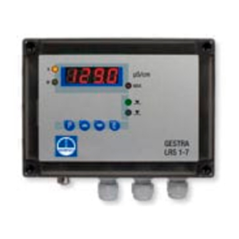
- Page 9 Dimensions / Functional Elements LRS 1-7 Fig. 2 Fig. 3...
- Page 10 Dimensions / Functional Elements - continued - LED 1: The actual value is shown on the seven-segment display LED 2: The setpoint is shown on the seven-segment display LED 3: MAX limit reached LED 4: The continuous blowdown valve opens LED 5: Continuous blowdown valve in operating position Seven-segment display, indication of actual value or setpoint, temperature, error code Pushbuttons...
-
Page 11: Conductivity Switch Lrs 1-7
Conductivity switch LRS 1-7 The housing of the conductivity switch LRS 1-7 is designed for wall mounting. To access the four fixing holes loosen the cover screws 8 and remove the housing cover 9. Attach the lower part of the housing by means of suitable screws and wall plugs. -
Page 12: Connecting Conductivity Switch Lrs 1-7
DIN 61010-1 or DIN EN 60730-1 or DIN EN 60950 between the current loop and live parts of the equipment that are not supplied with safety extra-low voltage (SELV). Connecting conductivity switch LRS 1-7 1. Undo cover screws 8 and remove the housing cover 9. (Fig. 2, 3) 2. -
Page 13: Wiring Diagram For Conductivity Switch Lrs 1-7 (Continuous Blowdown Control)
Electrical Connection - continued - Wiring diagram for conductivity switch LRS 1-7 (continuous blowdown control) LRS 1-7 P5 P4 P7A P7B P6 OPEN CLOSED Operation Actuator EF Contacts shown at Power OFF / limit exceeded condition Fig. 4 Conductivity switch with assignment of Current output 4-20 mA, load max. -
Page 14: Wiring Diagram For Conductivity Switch Lrs 1-7 (Water Monitoring)
Electrical Connection - continued - Wiring diagram for conductivity switch LRS 1-7 (water monitoring) LRS 1-7 P5 P4 P7A P7B P6 Valve OPEN: Fluid is flowing through Safety position: Valve CLOSED: Fluid is discharged Spring to close. or retained Contacts shown at... -
Page 15: Keys And Indicators
Commissioning Keys and indicators Functions of the pushbuttons Pushbutton 1 (P): Switches to parameterisation mode Pushbutton 2: Increases value –, scrolls up Pushbutton 3: Decreases value –, scrolls down Pushbutton 4 (E): Switches back to input mode and saves settings. Seven-segment display Indicates actual value or setpoint, temperature, error code LEDs 1 –... -
Page 16: Factory Setting
Commissioning - continued - Factory setting The conductivity switch LRS 1-7 features the following factory set default values: Setpoint W: 3000 µS/cm Temperature coefficient: 1.3 %/C MAX limit: 5000 µS/cm Unit: µS/cm Correction of measured value: 0,5 End of measuring range / output of actual value 6000 µS/cm = 20 mA... -
Page 17: Setting Parameters
Commissioning - continued - Setting parameters - continued - In the parameter 1. Setpoint set the switchpoint for the continuous blowdown valve to open. The continuous blowdown valve closes once the conductivity falls below the limit and the adjusted hysteresis. In the parameter 2. -
Page 18: Note
TDS (= total dissolved solids) level below the limit. The amount of boiler blowdown can be ascertained by means of the capacity charts for the continuous blowdown valve. Please observe the installation instructions of the GESTRA continuous blowdown valve. - Page 19 Malfunctions LRS 1-7 The following errors will be indicated on the seven-segment display: Error code Fault Remedy E.01 Connection line to conductivity Check connecting line and fasten electrode interrupted. Plug-in plug-in connector by tightening the connector has come loose. knurled nut.
-
Page 20: Fault Finding List For Troubleshooting
Malfunctions - continued - Fault finding list for troubleshooting Equipment does not work Fault: No voltage supply, no function. Remedy: Check voltage supply and all electrical connections. Fault: The electronic circuit board is defective. Remedy: Replace conductivity switch. Equipment signals a malfunction Error code: E.01 LED:... -
Page 21: Fault Finding List For Troubleshooting
Malfunctions - continued - Fault finding list for troubleshooting - continued - Equipment does not work correctly Fault: Indicated conductivity reading is larger than the reference value. Remedy: Change correction factor (3. Correction of measured value) and, if necessary, temperature coefficient (4.1 TK). Fault: Indicated conductivity reading is smaller than the reference value. -
Page 22: Danger
Decommissioning Danger The terminal strips of the conductivity switch LRS 1-7 are live during operation. This presents the risk of severe cases of electric shock! Always cut off power supply to the equipment before mounting, removing or connecting the terminal strips! Exchanging the conductivity switch 1. - Page 23 For your notes...
- Page 24 Agencies all over the world: www.gestra.de GESTRA AG Münchener Straße 77 28215 Bremen Germany Telefon +49 421 3503-0 Telefax +49 421 3503-393 E-mail info@de.gestra.com www.gestra.de 818872-02/07-2017cm (808782-02) · GESTRA AG · Bremen · Printed in Germany...
Need help?
Do you have a question about the LRS 1-7 and is the answer not in the manual?
Questions and answers