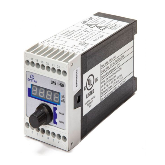
GESTRA LRS 1-50 Original Installation & Operating Manual
Conductivity switch
Hide thumbs
Also See for LRS 1-50:
- Installation instructions manual (20 pages) ,
- Original installation & operating manual (32 pages)

Related Manuals for GESTRA LRS 1-50


Summary of Contents for GESTRA LRS 1-50
- Page 1 Conductivity Switch LRS 1-50 Original Installation & Operating Manual 819223-03 E n g l i s h...
-
Page 2: Table Of Contents
In the system: Wiring the conductivity electrode Connecting an LRG 12-2, LRG 16-4, LRG 17-1 or LRG 19-1 conductivity electrode and TRG 5-.. resistance thermometer ....................13 Connecting an LRG 16-9 conductivity electrode ..................13 LRS 1-50 - Installation & Operating Manual - 819223-03... - Page 3 Checking the displays and function of the MIN/MAX output contacts .............18 Password protection ..........................19 Troubleshooting Indications, diagnosis and remedies ......................20 Further information Action against high-frequency interference ...................21 Replacing/taking the equipment out of service ..................21 Disposal ..............................21 LRS 1-50 - Installation & Operating Manual - 819223-03...
-
Page 4: Important Notes
The conductivity switch indicates when a MIN and MAX conductivity has been reached. The LRS 1-50 conductivity switch can be combined in a circuit with the LRG 12-1, LRG 16-4, LRG 16-9, LRG 17-1 and LRG 19-1 conductivity electrodes. -
Page 5: Safety Note
(installation, removal, connecting cables). Attention The name plate indicates the technical features of the equipment. Do not bring into ser- vice or operate any equipment that does not bear its own specific name plate. LRS 1-50 - Installation & Operating Manual - 819223-03... -
Page 6: Directives And Standards
VdTÜV Bulletin “Wasserüberwachung 100” (Water Monitoring 100) The LRS 1-50 conductivity switch, in combination with the LRG 1.-.. conductivity electrode, has type approval in accordance with VdTÜV Bulletin “Wasserüberwachung 100” (Water Monitoring 100), which describes the requirements for water monitoring equipment. -
Page 7: Technical Data
MAX limit: – 3% of set MAX limit Outputs LRS 1-50: 2 volt-free relay contacts, 8 A 250 V AC / 30 V DC cos ϕ = 1. Inductive loads must have interference suppression (RC combination) as per the manufacturer's specifications. -
Page 8: Product Package
Connection provided of conductivity on site electrode Power consumption IP rating External fuse for output contacts Measuring Supply range voltage Ambient Disposal temperature note Type approval number Output contacts Fig. 1 LRS 1-50 - Installation & Operating Manual - 819223-03... -
Page 9: Installation
The advantage of using the adapter is that the status is visible and alarms can be tested without open- ing the control cabinet door. When installed, the adapter has a rating of IP65. Please refer to the panel adapter Installation & Operating Manual 850625-xx for further information. LRS 1-50 - Installation & Operating Manual - 819223-03... -
Page 10: Dimensions Of Lrs 1-50
Installation continued Dimensions of LRS 1-50 Fig. 2 Upper terminal strip Housing Lower terminal strip Support rail TH 35, EN 60715 Installation in a control cabinet LRS 1-50 - Installation & Operating Manual - 819223-03... -
Page 11: In The Control Cabinet: Wiring The Conductivity Switch
The LRS 1-50 conductivity switch is clipped onto a type TH 35, EN 60715 support rail in the control cabinet. Fig. 1 4 In the control cabinet: Wiring the conductivity switch 0.5A 0.5A (semi- (semi- delay) delay) Fig. 3 Wiring diagram for conductivity switch LRS 1-50... -
Page 12: Supply Voltage Connection
Fig. 3. A pre-wired control cable (with plug and socket) is available in various lengths as an accessory for connecting the equipment. To connect the LRS 1-50 conductivity switch, please remove the connector and wire the terminal strip as shown in the wiring diagram. Fig. 3. -
Page 13: In The System: Wiring The Conductivity Electrode
This control cable is not UV-resistant and must be protected with a UV-resistant plastic tube or cable duct if the equipment is installed outdoors. To connect the LRS 1-50 conductivity switch, please remove the connector and wire the terminal strip as shown in the wiring diagram. Fig. 3 Connect the shield to the central earthing point (CEP) in the control cabinet. -
Page 14: Factory Settings
Put on the lower terminal strip. Switch the supply voltage back on. The equipment restarts. Fig. 4 Attention Do not change the settings of switches S1, S2 and S3 on code switch a! LRS 1-50 - Installation & Operating Manual - 819223-03... -
Page 15: Operating The Conductivity Switch
Temperature sensor defective, temperature reading too high E.005 Error Acquired reading defective, reading too low E.006 Error Acquired reading defective, reading too high E.013 Error MIN switchpoint higher than MAX switchpoint LRS 1-50 - Installation & Operating Manual - 819223-03... -
Page 16: Bringing Into Service
Or turn the rotary knob until the actual value is displayed. Or after 30s, the actual value is displayed automatically. If password protection is enabled, you must enter the password before you can change parameters. For the password, see page 19. LRS 1-50 - Installation & Operating Manual - 819223-03... -
Page 17: Setting Switchpoints And Parameters
In that Select correction factor CF, enter and save the required case, set the correction factor in increments until the value. displayed actual value matches the reference reading. LRS 1-50 - Installation & Operating Manual - 819223-03... -
Page 18: Operation, Alarm And Testing
You can interrupt the test sequence at any time by releasing the pushbutton. Test is displayed. Turn the rotary knob until the actual value is displayed. Or after 30s, the actual value is displayed automatically. LRS 1-50 - Installation & Operating Manual - 819223-03... -
Page 19: Password Protection
New calibration value has been accepted and donE a corresponding CF value calculated. Press and hold the pushbutton (on rotary knob). CF value is outside the admissible range. PF.Er Previous calibration has been retained. LRS 1-50 - Installation & Operating Manual - 819223-03... -
Page 20: Troubleshooting
In the event of a malfunction in the conductivity switch, the MIN and MAX alarm is trig- gered and the equipment restarts. If the process is continually repeated, the equipment must be replaced. LRS 1-50 - Installation & Operating Manual - 819223-03... -
Page 21: Further Information
In the event of malfunctions or faults that cannot be remedied with the aid of this Installation & Operat- ing Manual, please contact our service centre or authorised agent in your country. LRS 1-50 - Installation & Operating Manual - 819223-03... - Page 22 For your notes LRS 1-50 - Installation & Operating Manual - 819223-03...
- Page 23 For your notes LRS 1-50 - Installation & Operating Manual - 819223-03...
- Page 24 You can find our authorised agents around the world at: www.gestra.com GESTRA AG Münchener Straße 77 28215 Bremen Germany Tel. +49 421 3503-0 +49 421 3503-393 E-mail info@de.gestra.com Website www.gestra.com 819223-03/11-2021cm (808884-03) · GESTRA AG · Bremen · Printed in Germany...
Need help?
Do you have a question about the LRS 1-50 and is the answer not in the manual?
Questions and answers