
Subscribe to Our Youtube Channel
Related Manuals for GESTRA NRS 1-51


Summary of Contents for GESTRA NRS 1-51
- Page 1 GESTRA Steam Systems NRS 1-51 English Installation Instructions 818955-04 Level Switch NRS 1-51...
-
Page 2: Table Of Contents
Note on the Declaration of Conformity / Declaration by the Manufacturer ...........6 Functional Safety acc. to IEC 61508 Safety characteristics of the subsystem NRG 1...-51 / NRS 1-51 .............7 Terms and abbreviations .........................7 Determination of the Safety Integrity Level (SIL) for safety-related systems ..........8 Technical Data NRS 1-51............................ - Page 3 Connection of control circuit .........................14 Connection of logic unit (standby input)....................15 Connection for signal output .........................15 Tools ..............................15 Wiring diagram for level switch NRS 1-51 .....................16 Schematic representations of arrangements ..................17 Explanatory notes to schematic respresentations ..................17 Basic Settings Factory setting ............................17 Commissioning Procedure Checking switchpoint and function .......................18...
-
Page 4: Application
Application Usage for the intended purpose The level switch NRS 1-51 is used in conjunction with level electrodes NRG 1...-.. as high level alarm in steam boilers and (pressurised) hot-water plants. A high level alarm prevents the water level from exceeding the preset max. water level (HW) and for this purpose switches off e. -
Page 5: Directives And Standards
(pressurised) hot-water installations. Functional Safety acc. to IEC 61508 The level switch NRS 1-51 is certified acc. to IEC 61508 only if used in combination with level elec- trode NRG 1...-51. This standard describes the functional safety of safety-related electrical/electronic/ programmable electronic systems. -
Page 6: Atex (Atmosphère Explosible)
Directives and Standards – continued – ATEX (Atmosphère Explosible) According to the European Directive 2014/34/EU the level switch NRS 1-51 must not be used in potentially explosive areas. Note The level electrodes NRG 1...-51, NRG 1...-12 are simple items of electrical equipment as specified in EN 60079-11 section 5.7. -
Page 7: Functional Safety Acc. To Iec 61508
Functional Safety acc. to IEC 61508 Safety characteristics of the subsystem NRG 1...-51 / NRS 1-51 The level switch NRS 1-51 is certified acc. to IEC 61508 only if used in combination with level electrodes NRG 1...-51. The equipment combination NRG 1...-51 / NRS 1-51 corresponds to a type B subsystem with Safety Integrity Level (SIL) 3. -
Page 8: Determination Of The Safety Integrity Level (Sil) For Safety-Related Systems
Functional Safety acc. to IEC 61508 – continued – Determination of the Safety Integrity Level (SIL) for safety-related systems Level electrode, level switch and actuators (auxiliary contactors in control circuit) are subsystems and together constitute a safety-related system that executes a safety function. The specification of the safety-related characteristics Fig. -
Page 9: Technical Data
Technical Data NRS 1-51 Supply voltage 24 VDC +/– 20 %, 0.3 A; 100 – 240 VAC +10/–15 %, 47 – 63 Hz, 0.2 A (optional) External fuse 0.5 A (semi-delay) Power consumption 7 VA Response sensitivity (Electrical conductivity of water at 25 °C) >... -
Page 10: Nrs 1-51
Technical Data – continued – NRS 1-51 – continued – Further conditions: Ambient temperature when system is switched on: 0 ... 55 °C during operation: –10 ... 55 °C Transport temperature –20 ... +80 °C (< 100 hours), defrosting time of the de-energized equipment before it can be put into operation: 24 hours. -
Page 11: Name Plate / Marking
Technical Data – continued – Name plate / marking Type designation Safety note Supply voltage/ Protection Ambient temperature / sensitivity Wire link, Wiring provided on site diagram Control circuit Fuse, provided on site Type approval no. TÜV · SHWS · XX-423 Manufacturer Serial number Disposal note... -
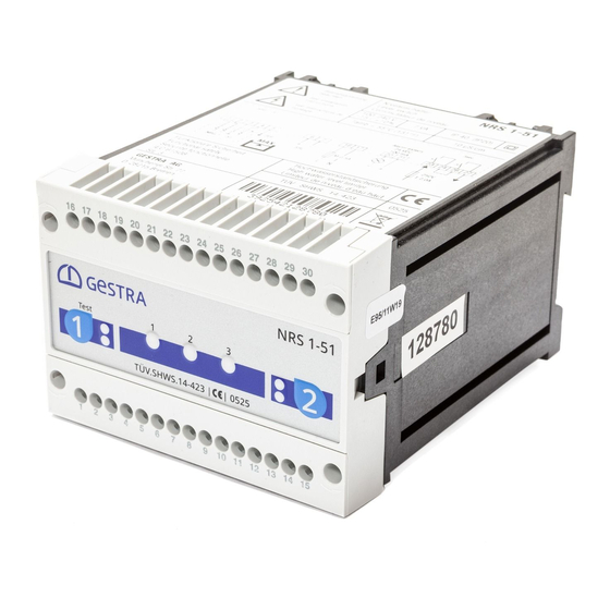
Page 12: Dimensions And Functional Elements
Dimensions and Functional Elements NRS 1-51 Fig. 6 Upper terminal strip Lower terminal strip Fixing screws (cross recess head screws M3) Enclosure Supporting rail type TH 35, EN 60715... -
Page 13: Important Notes
– have achieved a recognised level of competence. Danger The terminal strips of the NRS 1-51 are live during operation. This presents the danger of electric shock! Always cut off power supply to the equipment before mounting, removing or connecting... -
Page 14: Installation
Installation Mounting level switch NRS 1-51 The level switch NRS 1-51 is clipped onto the support rail 7 type TH 35, EN 60715 in the control cabinet. Fig. 6 Electrical Connection Connection of supply voltage Provide the level switch NRS 1-51 with an external semi-delay fuse 0.5 A. If the equipment is supplied with 24 V DC use a safety power supply unit with safe electrical isolation. -
Page 15: Connection Of Logic Unit (Standby Input)
(terminals 20, 21) closes instantaneously. Danger For the supply of the level switch NRS 1-51 with 24 V DC use a safety extra-low voltage (SELV) power supply unit that must be electrically isolated from dangerous contact voltages and must meet at least the requirements on double or reinforced iso- lation acc. -
Page 16: Wiring Diagram For Level Switch Nrs 1-51
– + M 0.5A 17 18 19 20 21 22 23 24 Test 11 12 * NRS 1-51 with response sensitivity 0.5 μS/cm: Connect the two internal screens to terminal 5 and the CEP. Fig. 7 Mains supply Signal output 1 for external alarm 24-230 V AC/DC 100 mA Control circuit, input and output Wire link, fitted on site, when used as high water level alarm acc. -
Page 17: Schematic Representations Of Arrangements
Steam boiler plants according to TRD 604, EN 12952-07 / EN 12953-06, 72 h operation Fig. 8 Combination consisting of 1 level electrode NRG 1...-51 and 1 level switch NRS 1-51 as high water level alarm. Functional safety IEC 61508, SIL 3. -
Page 18: Checking Switchpoint And Function
Commissioning Procedure – continued – Checking switchpoint and function Level electrode 1 Test & diagnosis TÜV . SHWS . 09-423 0525 button LED alarm 1 / operating mode Fig. 14 Diagnosis LED Start Activity Indication Function System is being started and tested, this takes All LEDs are illuminated. -
Page 19: Operation, Alarm And Test
Operation, Alarm and Test Indicators and adjustors Level electrode 1 Test & diagnosis TÜV . SHWS . 09-423 0525 button LED alarm 1 / operating mode Fig. 14 Diagnosis LED Operation Activity Indication Function Green LED Output contacts are closed. Level electrode exposed for level electrode 1 is illuminated Signal output 1 is open. - Page 20 Troubleshooting – continued – Indication, diagnosis and remedy – continued – Malfunction in level electrode Status and indication Fault Remedy Water level sufficient. Red LED for level electrode 1 is The insulation of the level Clean or, if necessary, replace level electrode. illuminated.
-
Page 21: Further Notes
HF interference suppression by means of hinged-shell ferrite rings. Interlock and interlock deactivation In the event of an alarm the level switch NRS 1-51 does not interlock automatically. If a lockout function is required by the installation it must be provided in the follow-up circuitry (control circuit). - Page 22 For your Notes...
- Page 23 For your Notes...
- Page 24 Agencies all over the world: www.gestra.de GESTRA AG Münchener Straße 77 28215 Bremen Germany Telefon +49 421 3503-0 Telefax +49 421 3503-393 E-mail info@de.gestra.com www.gestra.de 818955-04/04-2017csa (808806-04) · GESTRA AG · Bremen · Printed in Germany...
Need help?
Do you have a question about the NRS 1-51 and is the answer not in the manual?
Questions and answers