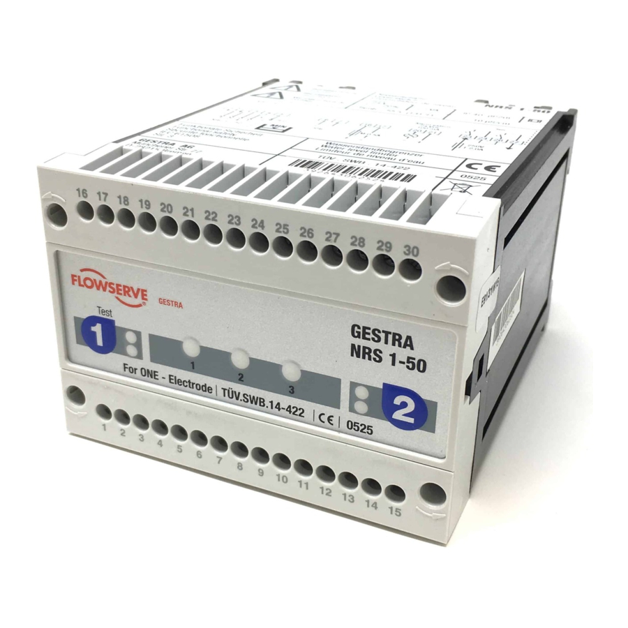
GESTRA NRS 1-50 Original Installation & Operating Manual
For two electrodes
Hide thumbs
Also See for NRS 1-50:
- Original installation & operating manual (32 pages) ,
- Original installation instructions (28 pages) ,
- Instruction manual (2 pages)

Related Manuals for GESTRA NRS 1-50


Summary of Contents for GESTRA NRS 1-50
- Page 1 Level Switch NRS 1-50 For TWO electrodes Original Installation & EN (USA) Operating Manual 850694-00 English...
-
Page 2: Table Of Contents
Wiring diagram for Class C protection against second faults with automatic prevention of interlock deactivation in the event of malfunction................22 Example switching combinations ....................23 Key to example switching combinations..................24 NRS 1-50 For TWO electrodes - USA - Installation & Operating Manual - 850694-00... - Page 3 Interlock and interlock deactivation ....................31 Checking switchpoints ........................31 Taking out of service .......................... 32 Disposal .............................. 33 Returning decontaminated equipment ....................33 UL components ........................... 33 NRS 1-50 For TWO electrodes - USA - Installation & Operating Manual - 850694-00...
-
Page 4: Content Of This Manual
The General Terms & Conditions of GESTRA AG apply. Scope of supply, product package NRS 1-50 1 level switch NRS 1-50 1 Installation & Operating Manual NRS 1-50 For TWO electrodes - USA - Installation & Operating Manual - 850694-00... -
Page 5: How To Use This Manual
How to use this Manual This Installation & Operating Manual describes the correct use of the NRS 1-50 level switch. It applies to persons who integrate this equipment in control systems, install, bring into service, op- erate, maintain and dispose of this equipment. Anyone carrying out the above-mentioned activities must have read this Installation &... -
Page 6: Types Of Warning
Warning of a situation that may result in minor or moderate injury. ATTENTION Warning of a situation that results in damage to property or the environment. NRS 1-50 For TWO electrodes - USA - Installation & Operating Manual - 850694-00... -
Page 7: Specialist Terms, Abbreviations
A boiler that is operated at 145 psi (10 bar) and 356°F (180°C) may be designed to withstand a pressure of 870 psi (60 bar) and a temperature of 527°F (275°C), for example, which is therefore not necessarily its operating point. NRS 1-50 For TWO electrodes - USA - Installation & Operating Manual - 850694-00... -
Page 8: Usage For The Intended Purpose
Water level limiters switch off the heating when the water drops below the set low water level (LW). The NRS 1-50 is classified as a protective control Class B (C) in accordance with UL 60730- When used as intended, the NRS 1-50 level switch is combined in a circuit with the level elec- trodes stipulated by the directives or standards below: Level electrodes NRG 1...-.. -
Page 9: Basic Safety Information
Check that the plant is not carrying live voltage before commencing work. ■ Attempts to repair the equipment will cause the plant to become unsafe. The NRS 1-50 level switch may only be repaired by the manufacturer, GESTRA AG. ■ Only replace faulty equipment with identical equipment from GESTRA AG. -
Page 10: Required Personnel Qualifications
Refits Specialist staff with pressure and temperature. Notes on product liability The manufacturer cannot accept any liability for damages resulting from improper use of the equipment. NRS 1-50 For TWO electrodes - USA - Installation & Operating Manual - 850694-00... -
Page 11: Function
Function The NRS 1-50 level switch is designed for boiler water conductivities of >=10 µS and for the connection of two or one level electrode(s). If the water falls below the minimum level, the level electrodes are exposed and an alarm is triggered in the level switch. -
Page 12: Technical Data
Max. 95%, non-condensing Site altitude Max. 6560 ft (2000 m) Other information Incorporated Type 2 action protective control Class B (C) Pollution degree 2, impulse voltage 2500 V NRS 1-50 For TWO electrodes - USA - Installation & Operating Manual - 850694-00... -
Page 13: Rating Plate, Identification
Use 60/75°C Conductors, E513189 Use No.18 16 AWG Wire Size Only, NRS 1-50 For TWO electrodes - USA - Installation & Operating Manual - 850694-00 Tightening: Torque 0.79Nm or 7lb in. Use with accessory: NRG 16,17,19,111 11, 50, 50(F), NRG 16 36... -
Page 14: Factory Default Settings
The level switch is delivered with the following factory default settings: Off delay: 3 s ■ Configuration: Operation with two NRG 1 ...-50 level electrodes. Code switches 4 and 5 in ■ OFF position (Fig. 3) NRS 1-50 For TWO electrodes - USA - Installation & Operating Manual - 850694-00... -
Page 15: Dimensions Of The Nrs 1-50
Code switch for switching level electrode 1 or 2 on/off Code switch for switching level electrode 1 or 2 on/off Terminal box Support rail TH 35, EN 60715 NRS 1-50 For TWO electrodes - USA - Installation & Operating Manual - 850694-00... -
Page 16: Important Notes
Attention Pay attention to regulations in your country, e.g., NEC, NFPA, CEC, when using this equipment. NRS 1-50 For TWO electrodes - USA - Installation & Operating Manual - 850694-00... -
Page 17: Preparing For Installation
Take further measures to protect the equipment from lightning, insects and ■ animals, and salty air. You will need the following tools: Pozidriv screwdriver PZ1 ■ NRS 1-50 For TWO electrodes - USA - Installation & Operating Manual - 850694-00... -
Page 18: Installation
ATTENTION Incorrect installation can lead to malfunctions in the plant or the level electrode. The NRS 1-50 level switch snaps onto a TH 35, EN 60715 support rail in a control cabinet. Fig. 3 7 NRS 1-50 For TWO electrodes - USA - Installation & Operating Manual - 850694-00... -
Page 19: Electrical Connection
24 and 26. Provide the output contacts with a slow blow T1A fuse. Note In the event of an alarm, the NRS 1-50 level switch interlock does not take place ■ automatically. -
Page 20: Connecting The Signal Output
A safety power supply unit (SELV / PELV / CLASS2) must be used to supply the ■ NRS 1-50 level switch with 24 V DC. This must provide a level of isolation against dangerous contact voltages that at least meets the requirements for double or reinforced insulation in accordance with UL 60730-1 (protective electrical isolation). -
Page 21: Wiring Diagram Of Level Switch Nrs 1-50
Signal output 1 / 2 for external alarm 24 V DC, 100 mA (semiconductor output) Safety circuit, input and output Jumper, provided by customer Level electrode NRG 1...-50 CGP Central grounding point in control cabinet NRS 1-50 For TWO electrodes - USA - Installation & Operating Manual - 850694-00... -
Page 22: Interlock Deactivation In The Event Of Malfunction
Reset IN Reset button 17 18 19 20 21 22 23 24 Signal 1 NRS 1-50/51 Test Signal 2 11 12 Reset OUT Fig. 5 NRS 1-50 For TWO electrodes - USA - Installation & Operating Manual - 850694-00... -
Page 23: Example Switching Combinations
Fig. 8 Fig. 9 Fig. 10 Fig. 11 Safety circuit Level electrode(s) NRG 1...-50 Level switch NRS 1-50 for advance low water alarm Level switch NRS 1-50 NRS 1-50 For TWO electrodes - USA - Installation & Operating Manual - 850694-00... -
Page 24: Key To Example Switching Combinations
The requirement for hot water installations to have two mutually independent water level limiters is satisfied by installing a combination consisting of one NRG 1...-50 + NRS 1-50 in the hot water generator and another in the pressure maintaining vessel or expansion tank, etc., depending on the type of pressurization. -
Page 25: Bringing Into Service
Level electrode 2 passive Note If only one level electrode is switched on, only the operating state and alarm ■ LEDs of the relevant channel light up. NRS 1-50 For TWO electrodes - USA - Installation & Operating Manual - 850694-00... -
Page 26: Checking The Switchpoint And Function
Check level electrode installation and make Upper pressure relief hole is sure that the level in the protective tube flooded. corresponds to the actual water level. NRS 1-50 For TWO electrodes - USA - Installation & Operating Manual - 850694-00... -
Page 27: Operation, Alarm And Test
Does the wiring conform to the wiring diagram and your chosen switching combination? Configuration: Are code switches 4 and 5 set correctly for the number of level electrodes? NRS 1-50 For TWO electrodes - USA - Installation & Operating Manual - 850694-00... - Page 28 Once the error has been rectified, the level switch reverts to normal operation. After troubleshooting, please switch the mains supply off and on again after approx. 5 s. NRS 1-50 For TWO electrodes - USA - Installation & Operating Manual - 850694-00...
-
Page 29: Checking The Level Electrode
Level electrode NRG 1...-50 CGP Central grounding point in control cabinet Note ■ The self-test of the NRS 1-50 level switch cyclically reduces U 2-4/10-12 possibly to 0 V. NRS 1-50 For TWO electrodes - USA - Installation & Operating Manual - 850694-00... -
Page 30: Emergency Mode
Emergency mode Emergency mode for water level limiters If the NRS 1-50 level switch works with two NRG 1...-50 level electrodes (water level limiters), the plant can continue running with just one level electrode, under constant supervision, if one level electrode drops out. -
Page 31: Important Notes
■ Suppress HF interference using hinged-shell ferrite rings. Interlock and interlock deactivation In the event of an alarm, the NRS 1-50 level switch interlock does not take place automatically. If the installation requires an interlock, this must be implemented in the external (safety) circuit. -
Page 32: Taking Out Of Service
Fig. 3 1 2 3. Release the white slider holder at the bottom of the unit and detach the unit from the support ■ rail. NRS 1-50 For TWO electrodes - USA - Installation & Operating Manual - 850694-00... -
Page 33: Disposal
Fill out the return confirmation (including declaration of decontamination) and send it with the products to GESTRA AG. UL components The NRS 1-50 level switch is registered under XACN.E513189. NRS 1-50 For TWO electrodes - USA - Installation & Operating Manual - 850694-00... - Page 34 For your notes NRS 1-50 For TWO electrodes - USA - Installation & Operating Manual - 850694-00...
- Page 35 For your notes NRS 1-50 For TWO electrodes - USA - Installation & Operating Manual - 850694-00...
- Page 36 You can find our authorized agents around the world at: www.gestra.com GESTRA AG Münchener Straße 77 28215 Bremen Germany Tel. +49 421 3503 0 +49 421 3503 393 e-mail info@de.gestra.com www.gestra.com 850694-00/09-2021cm (809138-00) · GESTRA AG · Bremen...
Need help?
Do you have a question about the NRS 1-50 and is the answer not in the manual?
Questions and answers