
Related Manuals for GESTRA LRGS 15-1


Summary of Contents for GESTRA LRGS 15-1
- Page 1 Conductivity Switch LRGS 15-1 Original Installation Instructions 818758-02 E n g l i s h...
-
Page 2: Table Of Contents
Attention ...............................12 Note ..............................12 Repositioning the terminal box ......................13 Mounting conductivity switch LRGS 15-1 ....................13 Tools ..............................13 Examples of Installation LRGS 15-1 used as conductivity electrode ....................14 LRGS 15-1 used for continuous blowdown control ................14, 15 Key ...............................15... - Page 3 Electrical Connection Aligning the terminal box ........................16 Connecting conductivity switch LRGS 15-1 ...................16 Attention ...............................17 Tools ..............................17 Wiring diagram for conductivity switch LRGS 15-1 ................18 Commissioning Keys and indicators ..........................19 Checking electrical connection ......................19 Applying mains voltage .........................19 Factory settings ............................20 Setting parameters .........................
-
Page 4: Important Notes
Important Notes Usage for the intended purpose The conductivity switch LRGS 15-1 must only be used for measuring the electrical conductivity in liquids. Safety note The equipment must only be installed by and commissioned by qualified and competent staff. Retrofitting and maintenance work must only be performed by qualified staff who – through adequate training –... -
Page 5: Explanatory Notes
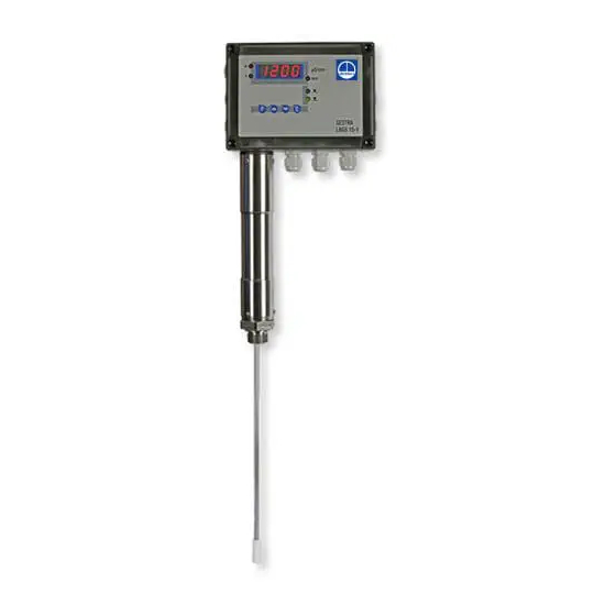
The conductivity switch LRGS 15-1 is a compact system consisting of a conductivity monitoring electrode and a conductivity switch integrated in the terminal box. The LRGS 15-1 is used as limit switch and continuous blowdown controller in steam boilers. The conductivity switch works according to the conductometric measuring method, continuously sensing the electrical conductivity of the boiler water and thus taking a direct measurement of the total dissolved solids (TDS). -
Page 6: Technical Data
Technical Data LRGS 15-1 Service pressure PN 25, 25 bar at 224 °C Mechanical connection Screwed ¾", EN ISO 228-1 Screwed ¾" NPT (optional) Materials Electrode body for screwing in place: 1.4571, X6CrNiMoTi17-12-2 or 1.4404, A 479 316 L (for NPT thread) Measuring electrode: 1.4571, X6CrNiMoTi17-12-2... -
Page 7: Lrgs 15-1
Technical Data – continued – LRGS 15-1 – continued – Indicators and adjustors 1 Four-digit, seven-segment indicator, red, for showing the actual value (X) / setpoint (W) and status & malfunction messages 2 Amber LEDs for indicating the actual value (X) / setpoint (W) 1 Red LED for indicating the MAX limit 2 green LEDs for indicating “Valve OPEN / CLOSED”... -
Page 8: Name Plate / Marking
Safety note power supplies. See installation instructions! Avant d'ouvrir le couvercle dèconnecter complètement l'appareil. Voir instructions de montage. Equipment designation LRGS 15-1 Leitfähigkeitsschalter Conductivity Switch Commutateur de conductibilité Length of installation L: ____________ mm Pressure class, thread type, PN 25 1.4571... -
Page 9: Dimensions
Technical Data – continued – Dimensions ∅ 40 G ¾ ISO 228-1 RA 3.2 Fig. 2... -
Page 10: Functional Elements
Functional Elements LRGS 15-1 Fig. 3 P10 P11 Fig. 4... -
Page 11: Key
Dimensions / Functional Elements – continued – LED 1:The seven-segment indicator shows the setpoint LED 2: The seven-segment indicator shows the actual value LED 3: MAX limit reached LED 4: Continuous blowdown valve opens LED 5: Continuous blowdown valve in operating position Seven-segment indicator (indication of actual value or setpoint, temperature, error code) Pushbuttons Gasket... -
Page 12: Installation
Installation Attention Do not bend the measuring electrode during installation. Do not subject electrode to shocks. Note that the measuring electrode of the conductivity switch must not be cut! The conductivity switch is designed for installation in a boiler standpipe. ... -
Page 13: Repositioning The Terminal Box
5. Connect electrode cables to terminal lugs according to the wiring diagram, Fig. 8. 6. Replace cover I and fasten cover screws H. Mounting conductivity switch LRGS 15-1 1. Check sealing surfaces of boiler standpipe or flange (see Fig. 2) and, if necessary, re-finish them as specified in the drawing. -
Page 14: Examples Of Installation
Examples of Installation LRGS 15-1 used as conductivity electrode ~ 250 ¾" to ISO 228-1 LRGS 15-1 Fig. 5 LRGS 15-1 used for continuous blowdown control ~ 250 ¾" to ISO 228-1 LRGS 15-1 [mm] [mm] Fig. 6... -
Page 15: Key
Examples of Installation – continued – LRGS 15-1 used for continuous blowdown control Outlet ¾" to ISO 228-1 DN 15-40 LRGS 15-1 Inlet DN 15-40 Fig. 7 Joint ring 27 x 32, form D, DIN 7603, 2.4068, bright annealed Boiler drum... -
Page 16: Electrical Connection
3. Tighten fixing nut J with a torque of 25 Nm. 4. Replace cover I and tighten cover nuts J. Connecting conductivity transmitter LRGS 15-1 Multi-core flexible control cable (CSA of conductor: 0.75 – 1.5 mm ) can be used for wiring. -
Page 17: Attention
Electrical Connection – continued – Attention Note that the following basic insulated lines must not be installed in extra-low voltage areas: mains and control lines. To prevent the welding together of contacts provide an external slow-blow fuse T 2 A ... -
Page 18: Wiring Diagram For Conductivity Switch Lrgs 15-1
Electrical Connection – continued – Wiring diagram for conductivity switch LRGS 15-1 LRGS 15-1 Alarm ϑ Temp. μS feeler Pt 100 9 10 5 4 11 Closed Open Operation Fig. 8 Actuator EF 1 / EF 06 S1 Disconnector F1 Fuse for output contact... -
Page 19: Commissioning
Commissioning Keys and indicators Function of the keys Key 1 (P): For entering parameter setting mode Key 2: Decrease value, scroll up Key 3: Increase value, scroll down Key 4 (E): Leave parameter setting mode, return to input mode and save settings 7 Segment display Indicating actual value or setpoint, temperature, error code LEDs 1 –... -
Page 20: Factory Settings
Commissioning – continued – Factory settings When the conductivity switch LRGS 15-1 I started, it has the following default settings: Setpoint: 5000 µS/cm MAX limit: 8000 µS/cm Correction of measured value (CF): 0.2 PT 100: OFF ... - Page 21 Commissioning – continued – Setting parameters – continued – Correcting measured value by performing a reference measurement Measure the electrical conductivity of the boiler water sample (at 25 °C). Once the operating temperature is reached, change the correction factor indicated in the parameter ...
-
Page 22: Operation
Operation LRGS 15-1 Start Mains voltage L is Indication of actual value, Continuous blowdown valve is switched on LED 2 is illuminated and actuated for 120 sec. and opens LED 4 is flashing After 120 sec: Indication of actual value, LED 2 Continuous blowdown valve is Actual value <... -
Page 23: Troubleshooting
Troubleshooting Fault finding list Equipment is not working Fault: Failure of power supply, no function. Remedy: Check voltage supply and all electrical connections. Fault: Electronic insert is defective. Remedy: Replace terminal box and electronic insert. The equipment signals a malfunction Error code: E.01. -
Page 24: Cleaning Measuring Electrode, Exchanging Terminal Box
Before mounting, servicing or removing the equipment make sure that it has cooled down to room temperatures. The terminal strips of the conductivity switch LRGS 15-1 are live during operation. This presents the danger of electric shock. -
Page 25: Removing Conductivity Switch
Removing conductivity switch Removing and disposing of conductivity switch Before removing the conductivity switch take it out of service and cut off its power supply. 1. Unscrew the cover screws H and remove the cover I, Fig. 3, 4. 2. Detach the connecting wires from the terminal strips M and pull the wires out of the cable glands. 3. - Page 26 For your notes...
- Page 27 For your notes...
- Page 28 Agencies all over the world: www.gestra.de GESTRA AG Münchener Straße 77 28215 Bremen Germany Telefon +49 421 3503-0 Telefax +49 421 3503-393 E-mail info@de.gestra.com www.gestra.de 818758-02/07-2017cm (808760-02) · GESTRA AG · Bremen · Printed in Germany...
Need help?
Do you have a question about the LRGS 15-1 and is the answer not in the manual?
Questions and answers