
Related Manuals for GESTRA NRGS 15-1


Summary of Contents for GESTRA NRGS 15-1
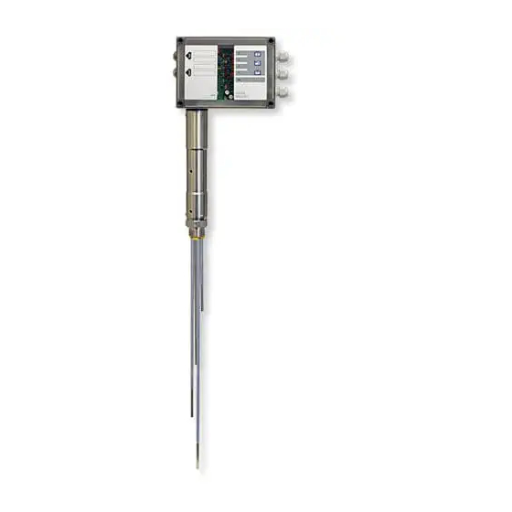
- Page 1 Level switch NRGS 15-1 Original Installation Instructions 818479-04 E n g l i s h...
-
Page 2: Table Of Contents
ATEX (Hazardous Area) ..........................6 UL/cUL (CSA) Approval ..........................6 Note on the Declaration of Conformity / Manufacturer's Declaration ..........6 Technical Data Level switch NRGS 15-1 .........................7 Scope of supply ............................8 Name plate / marking ..........................9 Dimensions ............................10 Establishing Functions Selecting function ..........................11 Level switch NRGS 15-1 ........................12... - Page 3 Contents - continued - Page Electrical connection Level switch NRGS 15-1 ........................19 Connecting level switch NRGS 15-1 .....................19 Wiring diagram .............................20 Tools ..............................20 Commissioning procedure Checking electrical connection ......................21 Applying supply voltage.........................21 Checking switchpoints and functions ....................21 Checking switchpoints and functions ....................22 Checking switchpoints and functions ....................23...
-
Page 4: Important Notes
MIN and MAX alarm. Function The level switch NRGS 15-1 is a complete package consisting of a four-tipped level electrode and an integrated level switching controller. The equipment works only with water having a min. electrical con- ductivity of >... -
Page 5: Safety Note
Important notes - continued - Safety note The equipment must only be installed and commissioned by qualified and competent staff. Retrofitting and maintenance work must only be performed by qualified staff who - through adequate training - have achieved a recognised level of competence. Danger When loosening the level electrode steam or hot water might escape. -
Page 6: Directives And Standards
For details on the conformity of our equipment with European Directives, please refer to our Declaration of Conformity or our Manufacturer's Declaration. The current Declaration of Conformity / Declaration of Manufacturer are available in the Internet under www.gestra.de/documents or can be requested from us. -
Page 7: Technical Data
Technical Data Level switch NRGS 15-1 Service pressure PN 25, 25 bar at 224°C Mechanical connection Screwed G 1A, ISO 228 Materials Screw-in body: 1.4571, CrNiMoTi17-12-2 or 1.4404, A 470 316L for NPT thread Electrode rods: 1.4571, CrNiMoTi17-12-2 Insulation of electrode rod: PTFE... -
Page 8: Scope Of Supply
Technical Data - continued - Level switch NRGS 15-1 - continued - Cable entry / electrical connection 3 cable glands with integral cable clamps (M 16) 1 two-pole terminal strip for power supply. 1 twelve-pole terminal strip for connecting the control cables. -
Page 9: Name Plate / Marking
Avant d'ouvrir le couvercle Avant d'ouvrir le couvercle dèconnecter complètement l'appareil. dèconnecter complètement l'appareil. Voir instructions de montage. Voir instructions de montage. Equipment designation NRGS 15-1 NRGS 15-1 Niveauschalter Niveauschalter Level switch Level switch Commutateur de niveau Commutateur de niveau... -
Page 10: Dimensions
Technical Data - continued - Dimensions b = 60 ∅ 42 G 1A, ISO 228 Fig. 2... -
Page 11: Establishing Functions
Establishing Functions Selecting function Before installing and commissioning the NRGS 15-1 ascertain the settings for the required functions. Five functions are available: Function 1 Code switch Default factory setting for equipment without pushbutton Toggle switch white 1 2 3 6 7 8 910... -
Page 12: Level Switch Nrgs 15-1
Establishing Functions - continued - Level switch NRGS 15-1 Fig. 3 & 1234 § " Fig. 4... -
Page 13: Establishing Functions
Establishing Functions - continued - Note To set the functions, the time delay and the response sensitivity open the terminal box. To do so unscrew the cover screws ( and remove the housing cover ). After changing the settings replace the housing cover )and fasten the cover screws (. Establishing functions 1. -
Page 14: Adjusting Sensitivity Range
Establishing Functions - continued - Adjusting sensitivity range The default factory setting for the response sensitivity is ≥ 10 μS/cm. If the electrical conductivity of the boiler water is below 10 μS/cm at 25°C use the code switch & to change the response sensitivity. -
Page 15: Installation
Installation Note For the approval of the boiler standpipe the relevant regulations must be considered. Refer to page 18 for typical installation examples. Attention Install the level switch only in a vertical position. The seating surfaces of the standpipe or the flange provided on the vessel must be accurately machined, Fig. -
Page 16: Nrgs 15-1
Installation - continued - NRGS 15-1 ∅ 40 G 1A, ISO 228 Ra 3.2 Fig. 5 Fig. 6... -
Page 17: Nrgs 15-1, Step 1
Installation - continued - NRGS 15-1, step 1 1. Determine the measuring lengths of the electrode tips and enter the lengths in the table "Functions". 2. Cut the electrode tips 1 2 3 4 to lengths with a bolt cutter. -
Page 18: Examples Of Installation
Installation - continued - Examples of installation 1" 1" DN 50 DN 50 ≤ 90° ≤ 90° ∅20 ∅20 Fig. 8 Fig. 7 Flange PN 40, DN 50, DIN EN 1092-01 or Protection tube DN 80 flange PN 40, DN 100, DIN EN 1092-01 Low water LW For the approval of the boiler standpipe with Reducer DIN 2616-2,... -
Page 19: Electrical Connection
+/- 180° into the desired direction (cable gland). Connecting level switch NRGS 15-1 1. Undo the cover screws ( and remove the housing lid ). Fig. 3, 9 2. Detach the terminal strips 6 and 8 from the electronic module. -
Page 20: Wiring Diagram
Electrical connection - continued - Wiring diagram TEST RESET Electrode wires PE connection S2 Disconnector F1 Fuse for level switch Mains supply Fig. 9 Tools Screwdriver, size 2 Screwdriver, size 2.5, completely insulated according to VDE 0680... -
Page 21: Commissioning Procedure
Electrical connection - continued - Attention n The following relocations of cables with basic insulation are not permissible: Mains and control cables in low voltage areas. n To prevent the welding together of contacts provide an external slow-blow fuse T 2.5 A for the output contacts.. -
Page 22: Checking Switchpoints And Functions
Commissioning procedure - continued - Checking switchpoints and functions Danger The terminal strip of the level switch is live during operation. This presents the danger of electric shock! Always cut off power supply to the equipment before mounting, removing or connecting the equipment and the terminal strips! Start Activity... -
Page 23: Checking Switchpoints And Functions
Commissioning procedure - continued - Checking switchpoints and functions Timed pump control (fill control) = electrode tip 3 Activity Display Function Lower water level until it is below the LED 3 illuminated switchpoint "Pump ON". Electrode rod 3 Pump output contact 10/12 closed, 10/11 open. amber emerges Fill vessel until switchpoint "Pump OFF"... -
Page 24: Troubleshooting
Troubleshooting Indication, diagnosis and remedy Attention Before carrying out the fault diagnosis please check: Supply voltage: Is the equipment supplied with the mains voltage specified on the name plate? Wiring: Is the wiring in accordance with the wiring diagram? Switchpoint MIN (low water) level Status and indication Error Remedy... -
Page 25: Indication, Diagnosis And Remedy
3. Undo the PE connection 0. 4. Unscrew the fixing screws 9 of the electronic module and take out the electronic module. The mod- ule is available as spare part. Stock code # NRGS 15-1 321357 NRV 1-47 230 V AC 5. -
Page 26: Removing And Disposing Of The Level Switch
Removing and disposing of the level switch Danger When loosening the level electrode steam or hot water might escape. This presents the danger of severe scalds to the whole body. Do NOT remove the level switch unless the boiler pressure is verified to be 0 bar. The level switch becomes hot during operation. -
Page 27: Annex
Annex Adjust other functions The level switch assigns one switching channel to each electrode tip. The functions of the switching channels 1 and 4 are fixed, the switchting channels 2 and 3 can be adjusted via code switch & to suit individual requirements. - Page 28 Agencies all over the world: www.gestra.de GESTRA AG Münchener Straße 77 28215 Bremen Germany Telefon +49 421 3503-0 Telefax +49 421 3503-393 E-mail info@de.gestra.com www.gestra.de 818479-04/08-17cm (808588-06) · GESTRA AG · Bremen · Printed in Germany...
Need help?
Do you have a question about the NRGS 15-1 and is the answer not in the manual?
Questions and answers