GESTRA LRS 1-50 Original Installation & Operating Manual
Conductivity switch
Hide thumbs
Also See for LRS 1-50:
- Installation instructions manual (20 pages) ,
- Original installation & operating manual (24 pages)

Related Manuals for GESTRA LRS 1-50


Summary of Contents for GESTRA LRS 1-50
- Page 1 Conductivity Switch LRS 1-50 Original Installation & EN (USA) Operating Manual 850704-01 English...
-
Page 2: Table Of Contents
Connecting conductivity electrode LRG 16-9 .................. 19 In the plant: Electrically connecting the conductivity electrode ............20 Connecting conductivity electrode LRG 16-4 .................. 20 Connecting conductivity electrode LRG 16-9 .................. 20 LRS 1-50 - USA - Installation & Operating Manual - 850704-01... - Page 3 Important notes ..........................29 Action against high-frequency interference ..................29 Taking out of service .......................... 30 Disposal .............................. 30 UL components ........................... 30 Declaration of Conformity Standards and directives ........................31 LRS 1-50 - USA - Installation & Operating Manual - 850704-01...
-
Page 4: Content Of This Manual
The General Terms & Conditions of GESTRA AG apply. Scope of supply, product package LRS 1-50 1 conductivity switch LRS 1-50 1 adhesive sign for ppm 1 Installation & Operating Manual LRS 1-50 - USA - Installation & Operating Manual - 850704-01... -
Page 5: How To Use This Manual
How to use this Manual This Installation & Operating Manual describes the correct use of the LRS 1-50 conductivity switch. It applies to persons who integrate this equipment in control systems, install, bring into service, op- erate, maintain and dispose of this equipment. Anyone carrying out the above-mentioned activities must have read this Installation &... -
Page 6: Types Of Warning
Warning of a dangerous situation that may possibly result in death or serious injury. CAUTION Warning of a situation that may result in minor or moderate injury. ATTENTION Warning of a situation that results in damage to property or the environment. LRS 1-50 - USA - Installation & Operating Manual - 850704-01... -
Page 7: Specialist Terms, Abbreviations
A boiler that is operated at 145 psi (10 bar) and 356°F (180°C) may be designed to withstand a pressure of 870 psi (60 bar) and a temperature of 527°F (275°C), for example, which is therefore not necessarily its operating point. LRS 1-50 - USA - Installation & Operating Manual - 850704-01... -
Page 8: Usage For The Intended Purpose
The conductivity switch indicates when a MIN and MAX conductivity has been reached. The LRS 1-50 is classified as an operating control in accordance with UL 60730-1. When used as intended, the LRS 1-50 conductivity switch can be combined in a circuit with the LRG 16-4 and LRG 16-9 conductivity electrodes. -
Page 9: Basic Safety Information
Check that the plant is not carrying live voltage before commencing work. ■ Attempts to repair the equipment will cause the plant to become unsafe. The LRS 1-50 conductivity switch may only be repaired by the manufacturer, GESTRA AG. ■ Only replace faulty equipment with identical equipment from GESTRA AG. -
Page 10: Required Personnel Qualifications
Persons trained by the plant operator to work Refits Specialist staff with pressure and temperature. Notes on product liability The manufacturer cannot accept any liability for damages resulting from improper use of the equipment. LRS 1-50 - USA - Installation & Operating Manual - 850704-01... -
Page 11: Function
Faults in the conductivity electrode or electrical connection and setting errors are shown on the 7-segment LED display. In the event of a malfunction, the MIN and MAX alarm is triggered. If faults occur only in the LRS 1-50 conductivity switch, the MIN and MAX alarm is triggered and the system is restarted. -
Page 12: Technical Data
-4 ° … 158 °F (-20 ° … +70 °C), only switch on after a defrosting period of 24 hours. Relative humidity Max. 95%, non-condensing Other information Incorporated type 1 action operating control Pollution degree 2, impulse voltage DC supply = 500 V, AC output = 2500 V LRS 1-50 - USA - Installation & Operating Manual - 850704-01... -
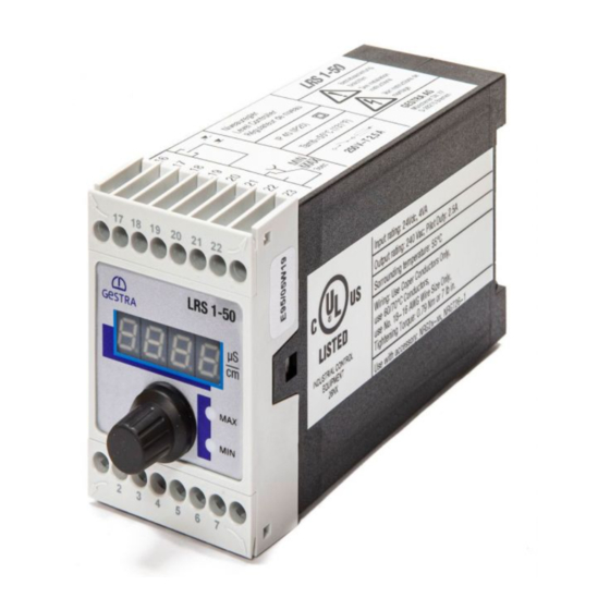
Page 13: Example Rating Plate/Identification
Wiring: Use Copper Conductors Only, OPERATING CONTROL Use 60/75°C Conductors, E513189 Use No.18 16 AWG Wire Size Only, Tightening: Torque 0.79Nm or 7lb in. Use with accessory: LRG 16-4, LRG 16-9 Fig. 1 LRS 1-50 - USA - Installation & Operating Manual - 850704-01... -
Page 14: Factory Default Settings
There is a risk of electric shock during work on electrical systems. Switch off the voltage to the plant before you install the equipment. ■ Check that the plant is not carrying live voltage before commencing work. ■ LRS 1-50 - USA - Installation & Operating Manual - 850704-01... -
Page 15: Dimensions Of The Lrs 1-50
Dimensions of the LRS 1-50 0.6 in (15 mm) 1.81 in (46 mm) 4.72 in (120 mm) Fig. 2 Upper terminal strip Terminal box Lower terminal strip Support rail TH 35, EN 60715 LRS 1-50 - USA - Installation & Operating Manual - 850704-01... -
Page 16: Preparing For Installation
Use UV-resistant cable ducts for routing the connecting cable. ■ Take further measures to protect the equipment from lightning, insects and ■ animals, and salty air. You will need the following tools: Screwdriver size 1/8 in (3.2 mm) ■ LRS 1-50 - USA - Installation & Operating Manual - 850704-01... -
Page 17: Installation
Installing the LRS 1-50 conductivity switch The LRS 1-50 conductivity switch snaps onto a TH 35, EN 60715 support rail in a control cabinet. Fig. 2 4 DANGER There is a risk of electric shock during work on electrical systems. -
Page 18: In The Control Cabinet: Electrically Connecting The Conductivity Switch
24 V DC with 0.5A medium time-lag cabinet fuse provided by customer MIN output contact Conductivity electrode LRG 1.-.. MAX output contact Conductivity electrode LRG 16-9 with integrated resistance thermometer LRS 1-50 - USA - Installation & Operating Manual - 850704-01... -
Page 19: Connecting The Supply Voltage
Connected inductive loads must therefore have interference sup- pression (RC combination) as specified by the manufacturer. If used as a conductivity limiter, the LRS 1-50 conductivity switch does not interlock automatically when the MAX limit is exceeded. -
Page 20: In The Plant: Electrically Connecting The Conductivity Electrode
To connect the LRS 1-50 conductivity switch, please remove the connector and wire the terminal strip as shown in the wiring diagram in Fig. 3. Generalized wire colors cannot be provided here, because the cables originate from different manufacturers. -
Page 21: Changing The Factory Default Settings
Insert the lower terminal strip. ■ Switch the supply voltage back on. The equipment restarts. ■ Attention Do not move switches S1, S2 and S3 on the code switch a! Fig. 4 LRS 1-50 - USA - Installation & Operating Manual - 850704-01... -
Page 22: Operating The Conductivity Switch
Faulty temperature sensor, temperature reading too high E.005 Error Faulty measured value acquisition, reading too low E.006 Error Faulty measured value acquisition, reading too high E.013 Error MIN switchpoint higher than MAX switchpoint LRS 1-50 - USA - Installation & Operating Manual - 850704-01... -
Page 23: Bringing Into Service
Or turn the rotary knob until the actual value is displayed. Or after 30 s, the actual value is displayed automatically. If password protection is enabled, you must enter the password before changing a parameter. See section on password protection. LRS 1-50 - USA - Installation & Operating Manual - 850704-01... -
Page 24: Setting Switchpoints And Parameters
In Select correction factor CF, enter and save the this case, change the correction factor in increments until required value. the indicated actual value matches the reference reading. LRS 1-50 - USA - Installation & Operating Manual - 850704-01... -
Page 25: Operation, Alarm And Test
You can cancel the test sequence at any time by releasing the display: Test is displayed. push-button. Turn the rotary knob until the actual value is displayed. Or after 30 s, the actual value is displayed automatically. LRS 1-50 - USA - Installation & Operating Manual - 850704-01... -
Page 26: Password Protection
Once disabled, password protection is reactivated after 30 minutes of no activity (i.e., rotary knob is not turned), and the password must be entered again. The parameters are password-protected when the equipment is restarted, if password protection was previously enabled. LRS 1-50 - USA - Installation & Operating Manual - 850704-01... -
Page 27: Calibration
Press and hold the push- and a CF value calculated on this basis. button (on rotary knob). CF value is outside the admissible range. The CF.Er previous calibration has been retained. LRS 1-50 - USA - Installation & Operating Manual - 850704-01... -
Page 28: Fault Indications And Troubleshooting
In the event of a fault in the conductivity switch, the MIN and MAX alarm is trig- gered and the equipment restarts. If the process repeats itself continuously, the equipment must be replaced. LRS 1-50 - USA - Installation & Operating Manual - 850704-01... -
Page 29: Important Notes
Installation & Operating Manuals. If equalizing currents are likely (outdoor installa- tions), connect the shield on one side only. Suppress HF interference using hinged-shell ferrite rings. ■ LRS 1-50 - USA - Installation & Operating Manual - 850704-01... -
Page 30: Taking Out Of Service
Release the white slider holder at the bottom of the unit and detach the unit from the support rail ■ Fig. 6 Disposal Dispose of the conductivity switch in accordance with statutory waste disposal regulations. UL components The LRS 1-50 conductivity switch is registered under XACN.E513189. LRS 1-50 - USA - Installation & Operating Manual - 850704-01... -
Page 31: Declaration Of Conformity Standards And Directives
Please see our Declaration of Conformity and associated certificates for details on the conformity of our equipment and the applicable standards and directives. You can download the Declaration of Conformity online at www.gestra.com or request certificates from the following address: GESTRA AG Münchener Straße 77... - Page 32 You can find our authorized agents around the world at: www.gestra.com GESTRA AG Münchener Straße 77 28215 Bremen Germany Tel. +49 421 3503 0 +49 421 3503 393 e-mail info@de.gestra.com www.gestra.com 850704-01/04-2022cm (809158-01) · GESTRA AG · Bremen...
Need help?
Do you have a question about the LRS 1-50 and is the answer not in the manual?
Questions and answers