
Related Manuals for GESTRA NRS 1-50


Summary of Contents for GESTRA NRS 1-50
- Page 1 GESTRA Steam Systems NRS 1-50 For ONE Electrode English Installation Instructions 818987-05 Level Switch NRS 1-50...
-
Page 2: Table Of Contents
ATEX (Atmosphère Explosible) .........................6 UL/cUL (CSA) Approval ..........................6 Functional Safety acc. to IEC 61508 Safety characteristics of the subsystem NRG 1...-50 / NRS 1-50 .............7 Terms and abbreviations .........................7 Determination of the Safety Integrity Level (SIL) for safety-related systems ..........8 Technical Data NRS 1-50............................9 –... - Page 3 Connection of safety circuit ........................14 Connection of logic unit (standby input)....................14 Connection for signal output .........................15 Tools ..............................15 Wiring diagram for level switch NRS 1-50 .....................16 Schematic representations of arrangements ..................17 Explanatory notes to schematic respresentations ..................18 Basic Settings Factory setting ............................19 Commissioning Procedure Checking switchpoint and function .......................20...
-
Page 4: Application
Application Usage for the intended purpose The level switch NRS 1-50 is used in conjunction with level electrode NRG 1...-.. to limit the water level in steam boilers and (pressurised) hot-water plants. Water level limiters switch off the heating when the water level falls below the set minimum level (low water). -
Page 5: Directives And Standards
Functional Safety acc. to IEC 61508 The level switch NRS 1-50 is certified acc. to IEC 61508 only if used in combination with level elec- trode NRG 1...-50 / NRG 16-36 . This standard describes the functional safety of safety-related electri- cal/electronic/programmable electronic systems. -
Page 6: Atex (Atmosphère Explosible)
Directives and Standards - continued - ATEX (Atmosphère Explosible) According to the European Directive 2014/34/EU the level switch NRS 1-50 must not be used in potentially explosive areas. Note The level electrodes NRG 1...-50, NRG 1...-11 and NRG 16-36 are simple items of electri- cal equipment as specified in EN 60079-11 section 5.7. -
Page 7: Functional Safety Acc. To Iec 61508
Functional Safety acc. to IEC 61508 Safety characteristics of the subsystem NRG 1...-50 / NRS 1-50 The level switch NRS 1-50 is certified acc. to IEC 61508 if used in combination with level electrode NRG 1...-50 / NRG 16-36. The combination NRG 1...-50 / NRG 16-36 / NRS 1-50 corresponds to a type B subsystem with Safety Integrity Level (SIL) 3. -
Page 8: Determination Of The Safety Integrity Level (Sil) For Safety-Related Systems
Functional safety acc. to IEC 61508 - continued - Determination of the Safety Integrity Level (SIL) for safety-related systems Level electrode, level switch and actuators (auxiliary contactor in safety circuit) are subsystems and together constitute a safety-related system that executes a safety function. The specification of the safety-related characteristics Fig. -
Page 9: Technical Data
Technical Data NRS 1-50 Supply voltage 24 VDC + / – 20 %, 0.3 A; 100 – 240 VAC +10 / –15 %, 47 – 63 Hz, 0.2 A (optional) External fuse 0.5 A (semi-delay) Power consumption 7 VA Response sensitivity (Electrical conductivity of water at 25 °C) >... -
Page 10: Nrs 1-50
Technical Data - continued - NRS 1-50 - continued - Ambient temperature when system is switched on: 0 ° ... 55 °C during operation: -10 ... 55 °C Transport temperature –20 ... +80 °C (< 100 hours), defrosting time of the de-energized equipment before it can be put into operation: 24 hours. -
Page 11: Name Plate / Marking
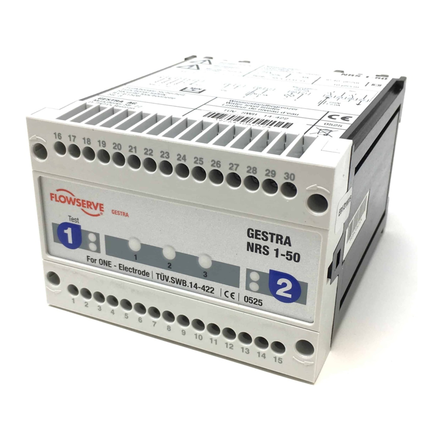
Technical Data - continued - Name plate / marking NRS 1-50 Niveauschalter Type designation Betriebsanleitung Level switch beachten Commutateur de niveau See installation Safety note Mains voltage/ instructions 100-240 V ~ IP 40 (IP20) 7 VA Protection -15 / +10%... - Page 12 Dimensions and Functional Elements NRS 1-50 16 17 18 19 20 21 22 23 24 25 26 28 29 30 Test 9 10 11 12 13 14 15 Fig. 6 Upper terminal strip Lower terminal strip Fixing screws (cross recess head screws M3)
-
Page 13: Important Notes
The name plate specifies the technical features of the equipment. Note that any piece of equipment without its specific name plate must neither be commissioned nor operated. Scope of supply NRS 1-50 1 Level switch NRS 1-50 1 Installation manual... -
Page 14: Installation
Installation Mounting level switch NRS 1-50 The level switch NRS 1-50 is clipped onto the support rail type TH 35, EN 60715 in the control cabinet. Fig. 6 5 Electrical Connection Supply voltage Fuse the level switch NRS 1-50 with an external semi-delay fuse 0.5 A. -
Page 15: Connection For Signal Output
(terminals 20, 21) opens instantaneously. Danger For the supply of the level switch NRS 1-50 with 24 V DC use a safety extra-low volt- age (SELV) power supply unit that must be electrically isolated from dangerous contact voltages and must meet at least the requirements on double or reinforced isolation acc. -
Page 16: Wiring Diagram For Level Switch Nrs 1-50
M 0,5A 17 18 19 20 21 22 23 24 Test Test 11 12 + – * NRS 1-50 with response sensitivity 0.5 μS: NRG 1..-50 Connect the two internal screens to terminal 5 and NRG 1..-11 the CEP. NRG 16-36 Fig. -
Page 17: Schematic Representations Of Arrangements
Electrical Connection - continued - Schematic representations of arrangements Fig. 9 Fig. 8 Fig. 10 Fig. 11 Level electrode NRG 1...-50 Safety circuit Level switch NRS 1-50 Level switch NRS 1-50 for low-level pre-alarm... -
Page 18: Explanatory Notes To Schematic Respresentations
EN 12952-07 / EN 12953-06, 72 h operation Fig. 8 Combination consisting of 1 level electrode NRG 1...-50 and 1 level switch NRS 1-50 as water level limiter. Functional safety IEC 61508, SIL 3. For operation according to TRD 604, EN 12952-07 / EN 12953-06 (72 hours), two independent and separate water level limiters must be used. -
Page 19: Basic Settings
Basic Settings Factory setting Level Switch NRS 1-50 The level switch features the following factory set default values: De-energizing delay: 3 sec., 15 sec. for marine applications. Commissioning Procedure Danger The terminal strips of the equipment are live during operation. -
Page 20: Checking Switchpoint And Function
Commissioning - continued - Checking switchpoint and function Test Test Level electrode Test & diagnosis Test & diagnosis button button LED alarm 1 / operating mode Fig. 12 Diagnosis LED Start Activity Indication Function System is being started and tested, this takes approx. -
Page 21: Operation, Alarm And Test
Operation, Alarm and Test Indicators and adjustors Test Test Level electrode Test & diagnosis Test & diagnosis button button LED alarm 1 / operating mode Fig. 12 Diagnosis LED Operation Activity Indication Function Green LED Output contacts are closed. Level electrode submerged. for level electrode is illuminated Signal output opens. - Page 22 Troubleshooting - continued - Indication, diagnosis and remedy - continued - Fault indication Status Diagnosis Function Next activity Output contacts are opened Faulty evaluation of level Diagnosis LED 1 and instantaneously. next: Press key 1. electrode, channel 1 LED alarm 1 illuminated. Signal output closes instantaneously.
-
Page 23: Checking Level Electrode
Stand-by input 1, 24 V DC, for connecting the logic unit SRL Level electrode NRG 1...-50, NRG 1...-11, NRG 16-36 CEP Central earthing point in control cabinet Note The self-checking routine of the level switch NRS 1-50 reduces U to 0 Volt, if executed cyclically. -
Page 24: Further Notes
HF interference suppression by means of hinged-shell ferrite rings. Interlock and interlock deactivation In the event of an alarm the level switch NRS 1-50 does not interlock automatically. If a lock function is required by the installation it must be provided in the follow-up circuitry (safety circuit). - Page 25 For your notes...
- Page 26 For your notes...
- Page 27 For your notes...
- Page 28 Agencies all over the world: www.gestra.de GESTRA AG Münchener Straße 77 28215 Bremen Germany Telefon +49 421 3503-0 Telefax +49 421 3503-393 E-mail info@de.gestra.com www.gestra.de 818987-05/04-2017csa (808835-05) · GESTRA AG · Bremen · Printed in Germany...
Need help?
Do you have a question about the NRS 1-50 and is the answer not in the manual?
Questions and answers