GESTRA LRS 1-50 Installation Instructions Manual
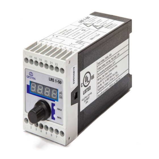
Conductivity switch
Hide thumbs
Also See for LRS 1-50:
- Original installation & operating manual (24 pages) ,
- Original installation & operating manual (32 pages)

Related Manuals for GESTRA LRS 1-50


Summary of Contents for GESTRA LRS 1-50
- Page 1 Conductivity Switch LRS 1-50 Original Installation Instructions 819223-02 E n g l i s h...
-
Page 2: Table Of Contents
Dimensions LRS 1-50 ..........................9 Key .................................9 Installation in control cabinet ........................9 In control cabinet: Wiring the conductivity switch Wiring diagram for conductivity switch LRS 1-50 ..................10 Key ...............................10 Connection of supply voltage .........................11 Connecting output contacts ........................11 Connecting conductivity electrode LRG 12-2, LRG 16-4, LRG 17-1 and LRG 19-1, resistance thermometer TRG 5-.. - Page 3 Contents - continued - Page Factory setting ............................13 Changing factory settings Switch selection of unit of measurement ....................13 Operating the conductivity switch Key to codes on seven-segment display ....................14 Commissioning procedure Setting parameters..........................15 Setting switchpoints and parameters ....................16 Operation, alarm and test Checking indication and functions of MIN / MAX output contacts ............17 Troubleshooting Indication, diagnosis and remedy ......................18...
-
Page 4: Important Notes
7-segment LED display. In the event of a malfunction a MIN and MAX alarm will be triggered. If an error occurs in the conductivity switch LRS 1-50, MIN and MAX alarms are raised and the system is restarted. -
Page 5: Safety Note
Important notes - continued - Safety note The equipment must only be installed, wired and commissioned by qualified and competent staff. Retrofitting and maintenance work must only be performed by qualified staff who - through adequate training - have achieved a recognised level of competence. Danger The terminal strips of the equipment are live during operation. -
Page 6: Directives And Standards
(pressurised) hotwater installations. VdTÜV Bulletin "Water Monitoring 100" The conductivity switch LRS 1-50 in conjunction with the conductivity electrode LRG 1.-.. is type ap- proved according to VdTÜV Bulletin "Water Monitoring 100".The VdTÜV Bulletin "Water Monitoring 100" states the requirements made on water monitoring equipment. -
Page 7: Technical Data
MAX limit: – 3 % of the adjusted MAX limit. Outputs LRS 1-50: 2 volt-free change-over contacts, 8 A 250 V AC / 30 V DC cos ϕ = 1. Provide inductive loads with RC combinations according to manufacturer's specification to ensure... -
Page 8: Scope Of Supply
Technical data - continued - LRS 1-50 - continued - Storage temperature –20 ... +70 °C, defrosting time of the de-energized equipment before it can be put into operation: 24 hours. Relative humidity max. 95%, no moisture condensation Approvals: TÜV certificate VdTÜV Bulletin "Wasserüberwachung 100"... -
Page 9: In Control Cabinet: Mounting The Conductivity Switch
Upper terminal strip Housing Lower terminal strip Supporting rail type TH 35, EN 60715 Installation in control cabinet The conductivity switch LRS 1-50 is clipped onto the support rail type TH 35, EN 60715 in the control cabinet. Fig. 1 4... -
Page 10: In Control Cabinet: Wiring The Conductivity Switch
In control cabinet: Wiring the conductivity switch Wiring diagram for conductivity switch LRS 1-50 M 0.5 A M 0.5 A (semi- (semi- delay) delay) Fig. 3 Connection of supply voltage 24 V DC Central earthing point (CEP) in control with fuse 0.5 A (semi-delay), provided on site cabinet Conductivity electrode LRG 1.-.. -
Page 11: Connection Of Supply Voltage
A-coded, pin assignment see Fig. 3. For connecting the equipment preconfigured control cable assemblies (with male and female connectors) of various lengths are available as add-on equipment. To connect the conductivity switch LRS 1-50 remove the connector and wire the terminal strip accord- ing to the wiring diagram. Fig. 3. -
Page 12: In The Plant
Note that the recommended control cable is not UV-resistant and, if installed outdoors, must be protected by a UV-resistant plastic tube or cable duct. To connect the conductivity switch LRS 1-50 remove the connector and wire the terminal strip accord- ing to the wiring diagram. Fig. 3 Connect the screen only once to the central earthing point (CEP) in the control cabinet. -
Page 13: Factory Setting
Factory setting Conductivity Switch LRS 1-50 Temperature compensation inP: No MAX switchpoint AL.Hi = 6000 μS/cm Temperature coefficient tC: 2.1 % / °C MIN switchpoint AL.Lo = 500 μS/cm Code switch a: All switches are set to Switching hysteresis: +/– 3% (fixed setting) OFF. -
Page 14: Operating The Conductivity Switch
Operating the conductivity switch Key to codes on seven-segment display 5432 Seven-segment display MAX LED Rotary button with integrated push- MIN LED button Fig. 5 Code Description Indicated when rotary button is turned to the right: AL.Hi Alarm High MAX switchpoint adjustable between 1 and 9999 μS/cm AL.Lo Alarm Low... -
Page 15: Commissioning Procedure
Commissioning procedure Setting parameters 5432 Seven-segment display MAX LED Rotary button with integrated push- MIN LED button Fig. 5 Start Activity Display Function Seven-segment display shows equipment and software ver- System test, takes approx. 3 sec. Switch on supply voltage. sion. -
Page 16: Setting Switchpoints And Parameters
Commissioning Setting switchpoints and parameters Setting MIN/MAX switchpoints Activity Function Select parameter AL.Lo, set the desired conductivity Adjust MIN limit between 1 and 9999 μS/cm or 1 and and save the setting. 5000 ppm. Select parameter AL.HI, set the desired conductivity and Adjust MAX limit between 1 and 9999 μS/cm or 1 and save the setting. -
Page 17: Operation, Alarm And Test
Operation, alarm and test Checking indication and functions of MIN / MAX output contacts 5432 Seven-segment display MAX LED Rotary button with integrated push- MIN LED button Fig. 5 Operation Activity Display Function The actual value is shown on Conductivity between MIN and the seven-segment display. -
Page 18: Troubleshooting
Troubleshooting Indication, diagnosis and remedy Attention Before carrying out the fault diagnosis please check: Supply voltage: Is the equipment supplied with the mains voltage specified on the name plate? Wiring: Is the wiring in accordance with the wiring diagram? Faults indicated by the seven-segment display Error code Error Remedy... -
Page 19: Further Notes
Further Notes Action against high frequency interference High frequency interference can occur for example as a result of out-of-phase switching operations. Should such interference occur and lead to sporadic failures, we recommend the following actions in order to suppress any interference. Provide inductive loads with RC combinations according to manufacturer's specification to ensure interference suppression. - Page 20 Agencies all over the world: www.gestra.de GESTRA AG Münchener Straße 77 28215 Bremen Germany Telefon +49 421 3503-0 Telefax +49 421 3503-393 E-mail info@de.gestra.com www.gestra.de 819223-02/02-2017cm (808884-02) · GESTRA AG · Bremen · Printed in Germany...
Need help?
Do you have a question about the LRS 1-50 and is the answer not in the manual?
Questions and answers