
Subscribe to Our Youtube Channel
Related Manuals for GESTRA NRGS 15-1


Summary of Contents for GESTRA NRGS 15-1
- Page 1 Level Switch NRGS 15-1 Original Installation & EN (USA) Operating Manual 850690-00 English...
-
Page 2: Table Of Contents
Installing the NRGS 15-1, step 2 ....................25 Installation examples with dimensions ..................... 26 Electrical connection .......................... 28 Rotating the terminal box ....................... 28 Connecting the NRGS 15-1 level switch ..................28 Wiring diagram ..........................29 NRGS 15-1 - USA - Installation & Operating Manual - 850690-00... - Page 3 Removing the level switch ......................35 Disposal .............................. 36 Returning decontaminated equipment ....................36 UL components ........................... 36 Annex ..............................37 Setting other functions ........................37 Installation in non-metallic tanks ....................37 NRGS 15-1 - USA - Installation & Operating Manual - 850690-00...
-
Page 4: Content Of This Manual
1 x NRGS 15-1 level switch, comprising ■ 1 x level electrode with four tips ■ 1 x terminal box with level switch ■ 1 x Installation & Operating Manual ■ NRGS 15-1 - USA - Installation & Operating Manual - 850690-00... -
Page 5: How To Use This Manual
How to use this Manual This Installation & Operating Manual describes the correct use of the NRGS 15-1 level switch. It applies to persons who integrate this equipment in control systems, install, bring into service, op- erate, maintain and dispose of this equipment. Anyone carrying out the above-mentioned activities must have read this Installation &... -
Page 6: Types Of Warning
Warning of a dangerous situation that may possibly result in death or serious injury. CAUTION Warning of a situation that may result in minor or moderate injury. ATTENTION Warning of a situation that results in damage to property or the environment. NRGS 15-1 - USA - Installation & Operating Manual - 850690-00... -
Page 7: Specialist Terms, Abbreviations
A boiler that is operated at 145 psi (10 bar) and 356 °F (180 °C) may be designed to withstand a pressure of 870 psi (60 bar) and a temperature of 527 °F (275 °C), for example, which is therefore not necessarily its operating point. NRGS 15-1 - USA - Installation & Operating Manual - 850690-00... -
Page 8: Usage For The Intended Purpose
The NRGS 15-1 is classified as an operating control in accordance with UL 60730-1. Applicable directives and standards The NRGS 15-1 level switch has been tested and approved for use in the scope governed by the following directives and standards: Standards: UL 60730-1 and CAN/CSA E60730-1 ■... -
Page 9: Basic Safety Information
Check that the level electrode is not leaking when bringing into service. ■ Attempts to repair the equipment will cause the plant to become unsafe. The NRGS 15-1 level switch may only be repaired by the manufacturer, GESTRA AG. ■ Only replace faulty equipment with identical equipment from GESTRA AG. -
Page 10: Required Personnel Qualifications
Persons trained by the plant operator to work Refits Specialist staff with pressure and temperature. Notes on product liability The manufacturer cannot accept any liability for damages resulting from improper use of the equipment. NRGS 15-1 - USA - Installation & Operating Manual - 850690-00... -
Page 11: Function
Function The NRGS 15-1 level switch is a compact system consisting of a level electrode with four tips and an integrated level switch. The equipment only functions if used in water with a minimum electrical conductivity of > 0.25 ppm (0.5 µS/cm) at 77 °F (25 °C). -
Page 12: Technical Data
Length supplied: 39.37 in (1000 mm) Diameter: 0.2 in (5 mm) Supply voltage NRGS 15-1 / 240 VAC: 240 V +10/–15 %, 50/60 Hz NRGS 15-1 / 120 VAC: 120 V +10/–15 %, 50/60 Hz Power consumption 3 VA Fuse... - Page 13 -4 ° ... 158 °F (-20 ° ... +70 °C), only switch on after a defrosting period of 24 hours. Relative humidity Max. 95%, no moisture condensation Weight Approx. 3.08 lb (1.4 kg) Other information Independently mounted Type 1.B action operating control Pollution degree 2, impulse voltage 4000 V NRGS 15-1 - USA - Installation & Operating Manual - 850690-00...
-
Page 14: Rating Plate, Identification
E513189 Fig. 1 Wiring: AWG 16-20, Cu only Output rating: Pilot Duty C300 / R300 Ambient temperature: 158°F (70°C) NRGS 15-1 - USA - Installation & Operating Manual - 850690-00 Input rating: 120VAC OPERATING CONTROL Environmental rating: NEMA 4 E513189... -
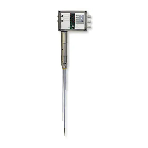
Page 15: Overall View Of The Nrgs 15-1
Overall view of the NRGS 15-1 Fig. 2 Terminal box with level switch Electrode rods Cover tube for four-tip Spacer level electrode Electrode thread NRGS 15-1 - USA - Installation & Operating Manual - 850690-00... -
Page 16: Dimensions Of The Nrgs 15-1
Dimensions of the NRGS 15-1 7.10 in (180 mm) w = 2.36 in (60 mm) Thermal insulation provided on site Size 41 1" - 11.5 NPT Fig. 3 NRGS 15-1 - USA - Installation & Operating Manual - 850690-00... -
Page 17: Setting Functions
1 2 3 6 7 8 910 Selecting a function Before installation and bringing into service, please decide which function you wish the NRGS 15-1 level switch to work with. Three functions are available: Function 1 Code switch Default factory setting... - Page 18 Setting functions Fig. 4 & 1234 " Fig. 5 NRGS 15-1 - USA - Installation & Operating Manual - 850690-00...
-
Page 19: Setting Functions
Terminal strip for control cables Cover screws (cross recess head screw M4) Cable gland M16 Cover of terminal box Terminal strip for supply voltage Fastening screws for electronic circuit board NRGS 15-1 - USA - Installation & Operating Manual - 850690-00... -
Page 20: Setting The Response Sensitivity
The sensitivity can be set as follows: Code switch Sensitivity White toggle switch 1 2 3 6 7 8 910 Sensitivity ≥ 5 ppm (10 µS/cm) at 77 °F (25 °C) (default) 1 2 3 6 7 8 910 NRGS 15-1 - USA - Installation & Operating Manual - 850690-00... -
Page 21: Preparing For Installation
You will need the following tools: Open-ended wrench size 41 ■ Scriber ■ Bolt cutter ■ Flat file ■ Phillips screwdriver PH2 ■ Flat blade screwdriver 3/32 in (2.4 mm) ■ NRGS 15-1 - USA - Installation & Operating Manual - 850690-00... -
Page 22: Installation
Make sure there is a creepage path of at least 0.55 in (14 mm) between the electrode ■ tips and ground (flange, tank wall). Figs. 8, 9, 10 Ensure minimum clearances when installing the electrode. ■ NRGS 15-1 - USA - Installation & Operating Manual - 850690-00... - Page 23 1" - 11.5 NPT Fig. 6 Thermal insulation (provided on site), d = 0.79 in (20 mm) (outside the thermal insulation of the steam generating unit) Thread 1" - 11.5 NPT Spacer NRGS 15-1 - USA - Installation & Operating Manual - 850690-00...
-
Page 24: Installing The Nrgs 15-1, Step 1
1.2 in (30 mm), measured from the lower edge of the screw thread. See Fig. 6. 5. Position the PTFE spacers evenly over the cut length. Functions table Wire/ Electrode tip Function Length [mm] connector NRGS 15-1 - USA - Installation & Operating Manual - 850690-00... -
Page 25: Installing The Nrgs 15-1, Step 2
(The band grounding clamp is available as an optional accessory) Next, measure the resistance again. The value must be < 10 ohms and entered as follows: Measured resistance: __________________________ ohms Boiler wall Visible thread Fig. 7 NRGS 15-1 - USA - Installation & Operating Manual - 850690-00... -
Page 26: Installation Examples With Dimensions
(49 mm) ≤ 90° ∅ 0.8 in (20 mm) Fig. 9 Protective tube (provided on site) when used as an internal water level controller in combination with a water level limiter NRGS 15-1 - USA - Installation & Operating Manual - 850690-00... - Page 27 Electrode rod Protective foam tube/level pot Electrode spacing ≥ 0.55 in Reducer (14 mm) (air gap and creepage path) Pressure relief hole CD center distance NRGS 15-1 - USA - Installation & Operating Manual - 850690-00...
-
Page 28: Electrical Connection
6. Plug terminal strips 6 and 8 into the electronic circuit board. 7. Tighten the cable glands 7 once more. 8. Put on the cover ) and tighten the cover screws (. NRGS 15-1 - USA - Installation & Operating Manual - 850690-00... -
Page 29: Wiring Diagram
Electrical connection Wiring diagram Electrode wires S2 disconnector F1 fuse for level switch Mains supply Fig. 12 Tools Phillips screwdriver PH2 ■ Flat blade screwdriver 3/32 in (2.4 mm) ■ NRGS 15-1 - USA - Installation & Operating Manual - 850690-00... -
Page 30: Bringing Into Service
1. Check switchpoints and functions by filling the tank and by draining some water, as appropri- ate. See the Checking switchpoints and functions table on pages 31 and 32. NRGS 15-1 - USA - Installation & Operating Manual - 850690-00... - Page 31 13/15 open. Drain water until it is below the MAX level. After 3s: MIN output contact 13/14 open, LED 4 is not lit Electrode rod 4 is exposed. 13/15 closed. NRGS 15-1 - USA - Installation & Operating Manual - 850690-00...
- Page 32 LED 3 is not lit exposed. Pump output contact 10/12 open, 10/11 closed. Drain water until it is below the Pump OFF switchpoint. Electrode rod 2 is LED 2 lights up exposed. NRGS 15-1 - USA - Installation & Operating Manual - 850690-00...
-
Page 33: Fault Indications And Troubleshooting
Check level switch installation and make sure For internal installation: The upper that the level in the protective tube corresponds pressure relief hole is flooded. to the actual water level. NRGS 15-1 - USA - Installation & Operating Manual - 850690-00... -
Page 34: Replacing The Electronic Circuit Board
When ordering spare parts, please state the material numbers on the rating plate. After you have replaced the electronic circuit board, please repeat the steps for bringing into service. NRGS 15-1 - USA - Installation & Operating Manual - 850690-00... -
Page 35: Taking Out Of Service
2. Disconnect all connecting cables from terminal strips 6, 8 and pull the cables out of the cable glands. 3. Make sure that the level switch is cold and not under pressure before removal. NRGS 15-1 - USA - Installation & Operating Manual - 850690-00... -
Page 36: Disposal
The term ‘media’ can refer to solid, liquid or gaseous substances or mixtures, as well as radiation. GESTRA AG can accept returned products only if accompanied by a completed and signed return note and also a completed and signed declaration of decontamination. -
Page 37: Annex
In this case, insert the connection of electrode rod into the free terminal lug for functional ground ". In addition, cut electrode rod to the same length as electrode rod and strip insulation over the entire length. NRGS 15-1 - USA - Installation & Operating Manual - 850690-00... - Page 38 For your notes NRGS 15-1 - USA - Installation & Operating Manual - 850690-00...
- Page 39 For your notes NRGS 15-1 - USA - Installation & Operating Manual - 850690-00...
- Page 40 You can find our authorized agents around the world at: www.gestra.com GESTRA AG Münchener Straße 77 28215 Bremen Germany Tel. +49 421 3503 0 +49 421 3503 393 e-mail info@de.gestra.com www.gestra.com 850690-00/08-2021cm (809122-00) · GESTRA AG · Bremen...
Need help?
Do you have a question about the NRGS 15-1 and is the answer not in the manual?
Questions and answers