
Subscribe to Our Youtube Channel
Related Manuals for GESTRA NRS 1-52


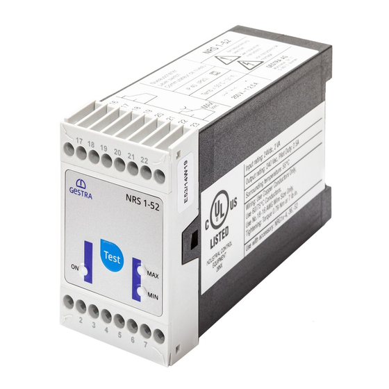
Summary of Contents for GESTRA NRS 1-52
- Page 1 Level Switch NRS 1-52 Original Installation Instructions 819176-02 E n g l i s h...
-
Page 2: Table Of Contents
Key .................................8 Installation in control cabinet ........................8 Example name plate / marking ........................9 In control cabinet: Wiring level switch Wiring diagram for level switch NRS 1-52 .....................10 Key ...............................10 Connecting supply voltage ........................11 Connecting MIN/MAX output contact .....................11 Connecting level electrode ........................11 Tools ..............................11... - Page 3 - continued - Page Operation, Alarm and Test Indicators and adjustors ........................17 Further Notes Action against high frequency interference ....................18 Decommissioning / replacing the equipment ..................18 Disposal ..............................18 Declaration of Conformity Directives and Standards ........................19 NRS 1-52 - Installation Instructions - 819176-02...
-
Page 4: Important Notes
Important Notes Usage for the intended purpose The level switch NRS 1-52 in conjunction with level electrodes NRG 1.-.. and ER 5. is used as limit switch, for instance in steam boilers, (pressurized) hot-water installations as well as condensate and feedwater tanks. -
Page 5: Potentially Explosive Areas
EN 60079-11 section 5.7. The equipment must be equipped with approved Zener barriers if used in potentially explo- sive areas. Applicable in Ex zones 1, 2 (1999/92/EC). The equipment does not bear an Ex marking. NRS 1-52 - Installation Instructions - 819176-02... -
Page 6: Technical Data
Electrical safety Pollution degree 2 for installation in control cabinet with protection IP 54, completely insulated Protection Housing: IP 40 to EN 60529 Terminal strip: IP 20 to EN 60529 Weight approx. 0.2 kg NRS 1-52 - Installation Instructions - 819176-02... -
Page 7: Scope Of Supply
–20 ... +70 °C, defrosting time of the de-energized equipment before it can be put into operation: 24 hours. Relative humidity max. 95 %, no moisture condensation Scope of supply NRS 1-52 1 Level switch NRS 1-52 1 Installation manual NRS 1-52 - Installation Instructions - 819176-02... -
Page 8: In Control Cabinet: Mounting Level Switch
Lower terminal strip Supporting rail type TH 35, EN 60715 Installation in control cabinet The level switch NRS 1-52 is clipped onto the support rail type TH 35, EN 60715 in the control cabinet. Fig. 1 NRS 1-52 - Installation Instructions - 819176-02... -
Page 9: Example Name Plate / Marking
8 Relay protection 9 Safety note 0 Manufacturer a Material number, serial number b Conformity mark c Disposal note d Type approval The date of production is printed on the side of the equipment. NRS 1-52 - Installation Instructions - 819176-02... -
Page 10: In Control Cabinet: Wiring Level Switch
In control cabinet: Wiring level switch Wiring diagram for level switch NRS 1-52 16 17 18 19 20 21 22 23 1 2 3 4 5 6 7 8 M 0.5 A (semi-delay) (–) (+) Fig. 3 Connection of supply voltage 24 V DC with fuse 0.5 A (semi-delay) provided on site... -
Page 11: Connecting Supply Voltage
Make sure that connecting cables leading to the level electrodes are segregated and run separately from power cables. Attention Do not use unused terminals as support point terminals. Tools For all functions: Screwdriver 0.8 x 4.0 or 0.8 x 4.5. NRS 1-52 - Installation Instructions - 819176-02... -
Page 12: In The Plant: Wiring Level Electrode
Level electrode ER 5.., 6 pole connector Level electrode NRG 10-52, NRG 16-52, five pole connector Level electrode NRG 16-4 Level electrode NRG 16-36 Central earthing point (CEP) in control cabinet Level electrode ER 5.., 4 pole connector NRS 1-52 - Installation Instructions - 819176-02... -
Page 13: Connection Of Level Electrode
In the plant: Wiring level electrode - continued - Connection of level electrode The level switch NRS 1-52 can be used in combination with the following level electrodes: Level electrodes NRG 10-52, NRG 16-36 NRG 16-4 ER 50 ER 56... -
Page 14: Commissioning Procedure
ON (= response sensitivity 0.5 µS/cm). Re-attach lower terminal strip. Apply supply voltage. Equipment is restarted. Fig. 9 Toggle switch, white Fig. 10 Attention Do not change the code switch settings of S1, S2 and S3! NRS 1-52 - Installation Instructions - 819176-02... -
Page 15: Checking Switchpoint And Function
Change response sensitivity to 0.5 μS/cm boiler water too low. Check installation of level electrode. Make sure Upper vent hole flooded. that the level in the protection tube corresponds to the actual water level. NRS 1-52 - Installation Instructions - 819176-02... - Page 16 Water level between MIN and MAX electrode rod is longer than Check and change the electrical connection of MAX. MIN and MAX LEDs are MIN electrode rod. the level electrode. flashing simultaneously. NRS 1-52 - Installation Instructions - 819176-02...
-
Page 17: Operation, Alarm And Test
Note: If you continue to hold down the Test button, a new test is started. button “Test”. Equipment You can abort the test any moment by releasing the Test button. returns to operating mode. NRS 1-52 - Installation Instructions - 819176-02... -
Page 18: Further Notes
For the disposal of the equipment observe the pertinent legal regulations concerning waste disposal. If faults occur that are not listed above or cannot be corrected, please contact our service centre or authorized agency in your country. NRS 1-52 - Installation Instructions - 819176-02... -
Page 19: Declaration Of Conformity Directives And Standards
For more information on the conformity of the equipment as well as applied Directives and Standards please refer to our Declaration of Conformity and associated certificates and/or approvals. The Declaration of Conformity can be found online at www.gestra.com and associated certificates can be requested from: GESTRA AG Münchener Straße 77... - Page 20 GESTRA UK Ltd Germany Telefon +49 421 3503-0 Unit 1 Sopwith Park, Royce Close, Telefax +49 421 3503-393 West Portway Business Park, Andover, E-mail info@de.gestra.com Hampshire SP10 3TS www.gestra.com United Kingdom 819176-02/07-2022cm[uk] (808832-02) · GESTRA AG · Bremen · Printed in Germany...
Need help?
Do you have a question about the NRS 1-52 and is the answer not in the manual?
Questions and answers