
Related Manuals for GESTRA NRS 1-53


Summary of Contents for GESTRA NRS 1-53
- Page 1 Level Switch NRS 1-53 Original Installation Instructions 819177-01 E n g l i s h...
-
Page 2: Table Of Contents
Connecting MIN 1 / MIN 2 output contact ....................11 Connecting level electrode ........................11 Tools ..............................11 In the plant: Wiring level electrode Connecting several level electrodes ......................12 Key ...............................12 Examples of configuration NRS 1-53 / NRS 1-54, connection of several level electrodes ....... 13 Connection of level electrode ........................14... - Page 3 Contents - continued - Page Factory settings Factory setting ............................14 Commissioning procedure Changing response sensitivity .......................15 Checking switchpoint and function ....................16 ,17 Operation, alarm and test Indications and operation ........................18 Further notes Protection against high frequency interference ..................19 Decommissioning / replacing the equipment ..................19 Disposal..............................
-
Page 4: Important Notes
Important Notes Usage for the intended purpose The level switch NRS 1-53 in conjunction with level electrodes NRG 1.-.. and ER 5. is used as limit switch, for instance in steam boiler and (pressurized) hot-water installations. The level switch detects and indicates two low water levels (MIN 1, MIN 2). -
Page 5: Directives And Standards
Directives and Standards VdTÜV Bulletin “Wasserstand 100” (= Water Level 100) The level switch NRS 1-53 in conjunction with level electrodes NRG 10-52, NRG 16-52, NRG 16-4 and ER 5.-1 is type approved to VdTÜV Bulletin “Water Level 100”. The VdTÜV Bulletin “Wasserstand (= Water Level) 100” specifies the requirements made on water level control and limiting equipment for boilers. -
Page 6: Technical Data
Technical data NRS 1-53 Supply voltage 24 VDC +/– 20 % Fuse external 0.5 A (semi-delay) Power consumption 2 VA Connection of level electrode 2 inputs for level electrode NRG 10-52, NRG 16-52, NRG 16-4 and ER 5.-1, 4 poles with screen Electrode voltage Response sensitivity (Electrical conductivity of water at 25 °C) -
Page 7: Scope Of Supply
TÜV certificate VdTÜV Bulletin “Water Lever 100”: Requirements made on water level limiting & control equipment. Type approval no. TÜV . WR/WB . XX-424 (see name plate) Scope of supply NRS 1-53 1 Level switch NRS 1-53 1 Installation manual... -
Page 8: In Control Cabinet: Mounting Level Switch
Upper terminal strip Housing Lower terminal strip Supporting rail type TH 35, EN 60715 Installation in control cabinet The level switch NRS 1-53 is clipped onto the support rail type TH 35, EN 60715 in the control cabinet. Fig. 1... -
Page 9: Name Plate / Marking
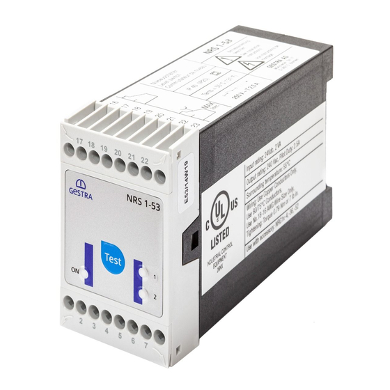
In control cabinet: Mounting level switch - continued - Name plate / marking Name plate (on top) Safety note Type designation Manufacturer Protection External fuse for output contacts Ambient temperature Output contacts Name plate (at the bottom) Fuse, provided on site Power consumption Connection of level electrodes... -
Page 10: In Control Cabinet: Wiring Level Switch
In control cabinet: Wiring level switch Wiring diagram for level switch NRS 1-53 M 0.5 A M 0.5 A (semi- (semi- delay) delay) (–) (+) (–) (+) Fig. 3 Connection of supply voltage 24 V DC with fuse 0.5 A (semi-delay) provided on site... -
Page 11: Connecting Supply Voltage
6 and 7 with a wire link. Fig. 3 Provide an external slow-blow fuse 2.5 A for the output contacts. When used as water level limiter the level switch NRS 1-53 does not interlock automatically when the water falls below the MIN level. -
Page 12: In The Plant: Wiring Level Electrode
In the plant: Wiring level electrode Connecting several level electrodes NRS 1-53 NRS 1-53 MIN 1 MIN 1 Fig. 4 Fig. 5 MIN 2 MIN 2 NRS 1-53 NRS 1-53 MIN 1 MIN 1 Fig. 6 Fig. 7 MIN 2... -
Page 13: Examples Of Configuration Nrs 1-53 / Nrs 1-54, Connection Of Several Level Electrodes
In the plant: Wiring level electrode - continued - Examples of configuration NRS 1-53 / NRS 1-54, connection of several level electrodes NRS 1-53 NRS 1-54 Fig. 8 NRS 1-53 NRS 1-54 Fig. 9 NRS 1-53 Fig. 10... -
Page 14: Connection Of Level Electrode
In the plant: Wiring level electrode - continued - Connection of level electrode The level switch NRS 1-53 can be used in combination with the following level electrodes: Level electrodes NRG 10-52, NRG 16-52, NRG 16-4, ER 50, ER 56,... -
Page 15: Commissioning Procedure
Commissioning procedure Danger The terminal strips of the equipment are live during operation. This presents the danger of electric shock! Always cut off power supply to the equipment before mounting, removing or connecting the terminal strips! Changing response sensitivity If the electrical conductivity of water is < 10 μS/cm at 25 °C change the response sensitivity as follows: Cut off supply voltage. -
Page 16: Checking Switchpoint And Function
Commissioning - continued - Checking switchpoint and function TEST button MIN 1 LED red/green LED “Power” MIN 2 LED red/green Fig. 12 Start Activity Display Function LED “Power” is illuminated. Switch on supply voltage. Water level between MIN and MIN 1 / MIN 2 electrode rods submerged or LED MIN 1 / MIN 2 illuminated MAX. -
Page 17: Checking Switchpoint And Function
Commissioning - continued - Checking switchpoint and function - continued - Possible installation faults Status and indication Error Remedy Cut electrode rods to the length required for the Electrode rods are too long. MIN 1 / MIN 2 switchpoint or Water level below MIN 1/ MIN 2 Cut electrode rod to the length required for MIN Electrode rod is too long. -
Page 18: Operation, Alarm And Test
Operation, Alarm and Test Indicators and adjustors Operation Activity Display Function Water level between MIN and LEDs MIN 1 and MIN 2 are MIN 1 output contact 21/23 open, 22/23 closed. MAX. illuminated green. MIN 2 output contact 16/18 open, 17/18 closed. MIN 1 and MIN 2 alarm (if 2 electrode rods are connected) MIN 1 LED flashes red. -
Page 19: Further Notes
Further Notes Action against high frequency interference High-frequency interference can be caused by out-of-phase switching operations. Should sporadic failures or malfunctions occur take the following remedial actions in order to suppress interference: Provide inductive loads with RC combinations according to manufacturer’s specification to ensure interference suppression. - Page 20 Agencies all over the world: www.gestra.de GESTRA AG Münchener Straße 77 28215 Bremen Germany Telefon +49 421 3503-0 Telefax +49 421 3503-393 E-mail info@de.gestra.com www.gestra.de 819177-01/02-2017cm (808848-01) · GESTRA AG · Bremen · Printed in Germany...
Need help?
Do you have a question about the NRS 1-53 and is the answer not in the manual?
Questions and answers