GESTRA NRS 1-50 Original Installation Instructions
Level switch
Hide thumbs
Also See for NRS 1-50:
- Original installation & operating manual (36 pages) ,
- Original installation & operating manual (32 pages) ,
- Instruction manual (2 pages)

Subscribe to Our Youtube Channel
Related Manuals for GESTRA NRS 1-50


Summary of Contents for GESTRA NRS 1-50
- Page 1 Level Switch NRS 1-50 For TWO Electrodes Original Installation Instructions 818953-08 E n g l i s h...
-
Page 2: Table Of Contents
Scope of supply ............................5 Potentially explosive areas ........................5 Functional Safety acc. to IEC 61508 Safety characteristics of the subsystem NRG 1...-50 / NRS 1-50 .............6 Terms and abbreviations .........................6 Determination of the Safety Integrity Level (SIL) for safety-related systems ..........7 Technical Data NRS 1-50 ..............................8... - Page 3 Action against high frequency interference ....................23 Interlock and interlock deactivation .......................23 Checking the switchpoints ........................23 Decommissioning / replacing level switch .....................23 Disposal ..............................23 Declaration of Conformity Directives and Standards ........................24 NRS 1-50 For TWO Electrodes - Installation Instructions - 818953-08...
-
Page 4: Important Notes
Important Notes Usage for the intended purpose The level switch NRS 1-50 is used in conjunction with level electrodes NRG 1...-.. to limit the water level in steam boilers and (pressurised) hot-water plants. Water level limiters switch off the heating when the water level falls below the set minimum level (low water). -
Page 5: Safety Note
1 Level switch NRS 1-50 1 Installation manual Potentially explosive areas The level switch NRS 1-50 must not be used in potentially explosive areas. Note The level electrodes NRG 1...-50, NRG 1...-11 and NRG 16-36 are simple items of electrical equipment as specified in EN 60079-11 section 5.7. -
Page 6: Functional Safety Acc. To Iec 61508
Functional Safety acc. to IEC 61508 Safety characteristics of the subsystem NRG 1...-50 / NRS 1-50 The level switch NRS 1-50 is certified acc. to IEC 61508 if used in combination with level electrode NRG 1...-50 / NRG 16-36 . -
Page 7: Determination Of The Safety Integrity Level (Sil) For Safety-Related Systems
SIL 3 60 % - < 90 % SIL 2 SIL 3 SIL 4 90 % - < 99 % SIL 3 SIL 4 SIL 4 ≥ 99 % Fig. 4 NRS 1-50 For TWO Electrodes - Installation Instructions - 818953-08... -
Page 8: Technical Data
Electrical safety Degree of contamination: 2, overvoltage category III to EN 61010-01. Protection Housing: IP 40 to EN 60529 Terminal strip: IP 20 to EN 60529 Weight approx. 0.5 kg NRS 1-50 For TWO Electrodes - Installation Instructions - 818953-08... - Page 9 –20 ... +70 °C, defrosting time of the de-energized equipment before it can be put into operation: 24 hours. Relative humidity max. 95 %, no moisture condensation Site altitude max. 2000 m NRS 1-50 For TWO Electrodes - Installation Instructions - 818953-08...
-
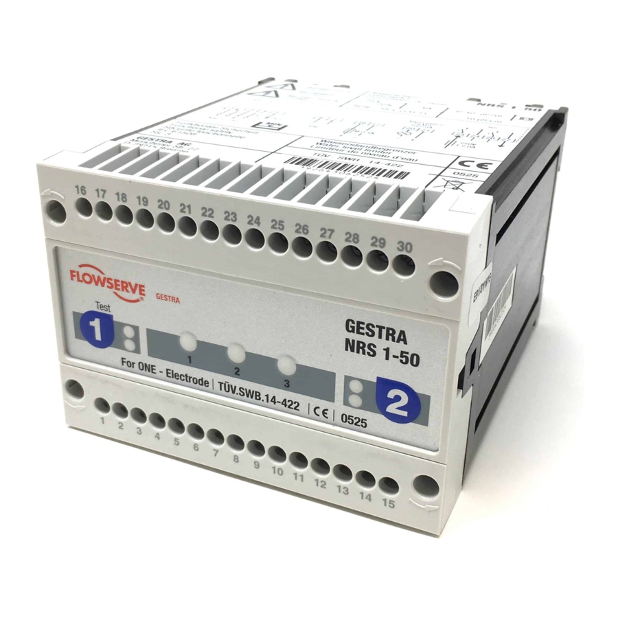
Page 10: Example Name Plate / Marking
9 Wiring diagram 0 Type approval no. a Material number, serial number b Manufacturer c Type approval d Disposal note The manufacturing date is shown at the side of the equipment. NRS 1-50 For TWO Electrodes - Installation Instructions - 818953-08... -
Page 11: Dimensions And Functional Elements
Fixing screws (cross recess head screws M3) Code switch for switching on/off level electrode 1 / 2 Code switch for switching on/off level electrode 1 / 2 Enclosure Supporting rail type TH 35, EN 60715 NRS 1-50 For TWO Electrodes - Installation Instructions - 818953-08... -
Page 12: Installation
Provide the output contacts with a 2 A or 1 A (for 72 hours operation) slow-blow fuse. Note In the event of an alarm the level switch NRS 1-50 does not interlock automatically. If a lock function is required by the installation it must be provided in the follow-up circuitry (safety circuit). -
Page 13: Connection For Signal Output
(terminals 20, 21 and 29, 30) open instantaneously. Danger For the supply of the level switch NRS 1-50 with 24 V DC use a safety extra-low voltage (SELV) power supply unit that must be electrically isolated from dangerous contact voltages and must meet at least the requirements on double or reinforced isolation acc. -
Page 14: Wiring Diagram For Level Switch Nrs 1-50
Stand-by input 1 / 2, 24 V DC, for connecting the logic unit SRL 6-50 Level electrode NRG 1...-50, NRG 1...-11 or NRG 16-36 CEP Central earthing point in control cabinet NRS 1-50 For TWO Electrodes - Installation Instructions - 818953-08... -
Page 15: Schematic Representations Of Arrangements
Schematic representations of arrangements Fig. 8 Fig. 9 Fig. 10 Fig. 11 Fig. 12 Fig. 13 Safety circuit Level electrode(s) NRG 1...-50 Level switch NRS 1-50 for low-level pre-alarm Level switch NRS 1-50 NRS 1-50 For TWO Electrodes - Installation Instructions - 818953-08... -
Page 16: Explanatory Notes To Schematic Respresentations
Combination consisting of 1 level electrode NRG 1...-50 and 1 level switch NRS 1-50 as water level limiter and 1 level electrode NRG 1...-50 / 1 level switch NRS 1-50 as first low-level alarm. Functional safety IEC 61508, SIL 3. -
Page 17: Basic Settings
OFF. Commissioning Procedure Danger The terminal strips of the NRS 1-50 are live during operation. This presents the danger of electric shock! Always cut off power supply to the equipment before mounting, removing or connecting the terminal strips! Changing configuration If only one electrode is used for operation (e. -
Page 18: Checking Switchpoint And Function
0.5 μS/cm. Check installation of level electrode. Make sure Upper vent hole flooded. that the level in the protection tube corresponds to the actual water level. NRS 1-50 For TWO Electrodes - Installation Instructions - 818953-08... -
Page 19: Operation, Alarm And Test
Is the wiring in accordance with the wiring diagram and the relevant schematic representation of arrangement? Configuration: Are the code switch settings correct for the number of level electrodes used? NRS 1-50 For TWO Electrodes - Installation Instructions - 818953-08... - Page 20 Once the fault is eliminated, the level switch returns to normal operation. After elimination of the fault switch off the mains voltage and switch it on again after approx. 5 sec. NRS 1-50 For TWO Electrodes - Installation Instructions - 818953-08...
-
Page 21: Measuring Voltage Across Level Electrode
Stand-by input 1 / 2, 24 V DC, for connecting the logic unit SRL Level electrode NRG 1...-50, NRG 1...-11, NRG 16-36 CEP Central earthing point in control cabinet Note The self-checking routine of the level switch NRS 1-50 reduces U to 0 Volt, 2-4/10-12 if executed cyclically. -
Page 22: Emergency Operation
Emergency operation Emergency operation for water level limiter If the level switch NRS 1-50 works with two level electrodes NRG 1...-50 (water level limiter to TRD 604, EN 12952-07, EN 12953-06), the installation can continue operating in emergency operation mode according to TRD 401 and EN 12952 and EN 12953 under constant supervision with only 1 level electrode, in case that one of the two installed level electrodes fails. -
Page 23: Further Notes
HF interference suppression by means of hinged-shell ferrite rings. Interlock and interlock deactivation In the event of an alarm the level switch NRS 1-50 does not interlock automatically. If a lock function is required by the installation it must be provided in the follow-up circuitry (safety circuit). -
Page 24: Declaration Of Conformity Directives And Standards
For more information on the conformity of the equipment as well as applied Directives and Standards please refer to our Declaration of Conformity and associated certificates and/or approvals. The Declaration of Conformity can be found online at www.gestra.com and associated certificates can be requested from: GESTRA AG Münchener Straße 77... - Page 25 For your notes NRS 1-50 For TWO Electrodes - Installation Instructions - 818953-08...
- Page 26 For your notes NRS 1-50 For TWO Electrodes - Installation Instructions - 818953-08...
- Page 27 For your notes NRS 1-50 For TWO Electrodes - Installation Instructions - 818953-08...
- Page 28 GESTRA UK Ltd Germany Telefon +49 421 3503-0 Unit 1 Sopwith Park, Royce Close, Telefax +49 421 3503-393 West Portway Business Park, Andover, E-mail info@de.gestra.com Hampshire SP10 3TS www.gestra.com United Kingdom 818953-08/07-2022cm[uk] (808805-09) · GESTRA AG · Bremen · Printed in Germany...
Need help?
Do you have a question about the NRS 1-50 and is the answer not in the manual?
Questions and answers