Table of Contents
Advertisement
Quick Links
Sports Art Industrial Co., Ltd. (Headquarter)
Sports Art America Inc.
#11, Gong Huan Road,
19510 144th Ave. N.E., Suite A-1,
Tainan City, Taiwan
Woodinville, WA 98072
T: 886 6 3840888
T: +1 425 4819479
F: 886 6 3840999
F: +1 425 4888155
info@sportsart.com.tw
info@gosportsart.com
Sports Art Europe, Middle East & Africa
Sports Art China
Strada Cantonale 42, Ch-6534 San Vittore,
Room 2202, BLDG. A, Huapu Garden,
Switzerland
Dongzhimen South Street, No. 9,
T: +41 91 8273908
Dongcheng District Beijing, 100007 China
F: +41 91 8273910
T: +86 10 84094122/84094123
giorgio365@ticino.com
F: +86 10 84094121
ISO 9001/14001 Certified
GoSportsArt.com
Sports Art Fitness UK Ltd.
Unit 2, 3 Charnwood Business Park,
North Road, Loughborough,
LE11 1LE, England
T: +44 1509 274440
ukinfo@gosportsart.com
2016.06
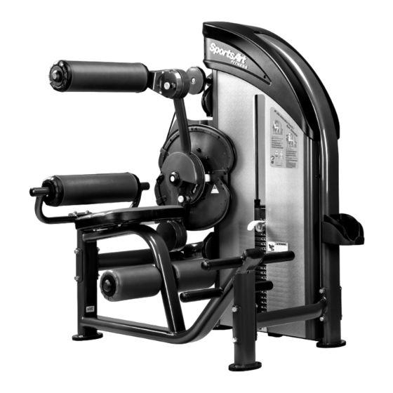
DF-206
Lower Back/Abdominal Crunch
Owner's Manual
Advertisement
Table of Contents

Related Manuals for SPORTS ART DF-206


Summary of Contents for SPORTS ART DF-206
- Page 1 F: 886 6 3840999 F: +1 425 4888155 T: +44 1509 274440 info@sportsart.com.tw info@gosportsart.com ukinfo@gosportsart.com Sports Art Europe, Middle East & Africa Sports Art China Strada Cantonale 42, Ch-6534 San Vittore, Room 2202, BLDG. A, Huapu Garden, Switzerland Dongzhimen South Street, No. 9,...
- Page 2 DF-206 OWNER’S MANUAL CONTENTS 1. INTRODUCTION ................2 2. SAFETY PRECAUTIONS ..............3. LIST OF PARTS ................. 4. ASSEMBLE THE PRODUCT ............. 10 STEP 1 Cover Support Plate and the Connector Installation ....10 STEP 2 Weight Stack Installation ............14 STEP 3 Apply the Weight Stack Sticker ..........
-
Page 3: Introduction
1. INTRODUCTION Congratulations on the purchase of a high quality SportsArt product, the DF-206 Lower Back / Abdominal Crunch machine. Constructed of high quality materials and designed for years of reliable performance, this product was made for full commercial use. -
Page 4: Safety Precautions
2. SAFETy PRECAUTIONS This product was designed and built for optimum safety. However certain precau- tions apply during the use of this product. Please note the following safety precau- tions: • Please read the entire manual before assembly and operation. Make sure the product is installed and operated as instructed in this manual. -
Page 5: List Of Parts
3. LIST OF PARTS Box A... - Page 6 Box B Box C...
- Page 7 Box A - Main Frame Components Name Qty. No. Name Qty. Weight stack top right A10 Bracket cover Weight stack top left A11 Cover cover Main frame A12 Rear cover Cover support plate B-2 A13 Front cover Cover support plate B-1 A14 Cover support plate A Stack fork A15 Floor fixing bracket...
- Page 8 Components in the Hardware Kit Name Qty. Specification Notes Mushroom top inner hex screw 12 M6*P1.0*L12 Mushroom top Phillips screw M5*L15 Screw socket SGN-07 Mushroom top Phillips screw 10 M5*0.8*L8 Round sticker Soft cap Inner hex screw M6*P1.0*L12 Bushing D19*7.8 Front cover bracket Phillips screw M6*P1.0*L12...
- Page 9 Components on the Product Name Specification Notes Hex head screw M8*P1.25*L65 Washer D17*d8.3*t2 PU tube ØD12*d8*L82 Nylon hex lock nut Guide rod Inner hex screw M8*P1.25*L18 Spring washer M8*t2.0 Washer D17*d8*t1.5 Inner hex screw Set fork Bolt assy. crossover Inner hex screw M8*P1.25*L20 Axle cover Ø65...
- Page 10 Components on the Product Name Specification Notes Inner hex screw M8*P1.25*L20 Spring washer Mushroom top inner hex screw M8*P1.25*L25 Inner hex screw M8*P1.25*L30 Spring washer Flat washer D22*d8.5*t3.0 Nylon hex lock nut Inner hex screw M8*P1.25*L30 Mushroom top inner hex screw M6*P1.0*L12 Mushroom top Phillips screw M5*0.8*L15...
-
Page 11: Assemble The Product
4. ASSEMBLE THE PRODUCT Follow instructions below to assemble this product. Note that in this manual the words “left” and “right” are used to refer to the product and its parts. As such, these designations correspond to the “left” and “right” sides of a person in position to exercise on this product. - Page 12 STEP 1 Cover Support Plate & Connector Installation (Cont.) (a) Insert the screw sockets (17) into place in the main frame (A3) as shown, and then use screws (15) (16) to secure the brackets (A9) (A10) in place. (Note: The bracket (A9) must be secured to the top of main frame as shown.)
- Page 13 STEP 1 Cover Support Plate & Connector Installation (Cont.) (b) Use screws (18) to secure the cover support plates (A14) to the straight frame of the main frame (A3) and then secure the cover support plates (A4) (A5) on both sides of the curved frame as shown. (Note: The cover support plates must be secured outside of the bracket (A9) (A10).)
- Page 14 STEP 1 Cover Support Plate & Connector Installation (Cont.) (c) Use screws (30) (31) to loosely secure the connecting board (A35) to the connector (A28), the main frame (A3) and the seat frame (A31) as shown. And then use screws (30) to loosely secure the connecting board (A35) to the connector B (A34), the main frame (A3) and the seat frame (A31) as shown.
-
Page 15: Step 2 Weight Stack Installation
STEP 2 Weight Stack Installation... - Page 16 STEP 2 Weight Stack Installation (Continued) Follow instructions (a) through (g) to install the weight stack. (a) Hold the upper stack carriage set (32), and then cut the zip tie. Gently lower the upper stack carriage set (32) into place as shown. (b) Remove screws (33) (34).
- Page 17 STEP 2 Weight Stack Installation (Continued) (d) Remove screws (36) from the stack fork (A6) and insert the weight stack rod (A7) into the central mounting position of the upper stack carriage set (32). Use screws (36) to secure the stack fork (A6) into place of the upper stack carriage set (32) as shown.
- Page 18 STEP 2 Weight Stack Installation (Continued) (f) Insert and lower the (5 kg/11lb) weight plate (A40) into place on the guide rods (35) one at a time. Once complete, slide down the upper stack carriage set (32) on top of the weight stack. (Note: The convex side of weight plate should face up and the stack fork (A6) points toward the front.) *If there is an optional (7.5kg/16.5lb) weight plate installed, insert the...
-
Page 19: Step 3 Apply The Weight Stack Sticker
STEP 3 Apply the Weight Stack Sticker Note: Before applying weight plate stickers, please wipe the area clean, and clean your hands before proceeding to the next step. (a) Align and tape the cardboard to the upper left corner of the weight plate (A40). -
Page 20: Step 4 Cam Installation
STEP 4 CAM Installation... - Page 21 STEP 4 CAM Installation (Continued) Follow instructions (a) through (f) to install the CAM. (a) Remove screws (40) and the axle cover (41) from the CAM (A21). (b) Place the CAM (A21) horizontally into its mounting area, and then rotate the CAM so that the rotator arm is pointing upward as shown.
- Page 22 STEP 4 CAM Installation (Continued) (d) Remove screws (42) from the CAM mounting area. (e) Secure the cover (A11) with screws (42). (Note: The bakelite must be rested below the cover as shown.) (f) Use screws (43) to secure the stopper A (A23) to the CAM (A21). (Note: The correct stopper position is indicated by the “O”...
-
Page 23: Step 5 Cable Installation
STEP 5 Cable Installation... - Page 24 STEP 5 Cable Installation (Continued) Follow instructions (a) through (c) to install the cable nut and the stack rod. (a) Insert the cable nut as indicated by the arrows onto the weight stack rod (A7) at least 20mm deep as shown. (b) Take out the stack fork (A6) and lift the upper stack carriage set (32) up.
- Page 25 STEP 5 Cable Installation (Continued) Follow instructions (a) through (d) to install the upper cable. (a) Remove screws (44) from the main frame (A3) and then install the pulley (A37) and thread the cable goes through the pulley (A37) as indicated by the arrows.
- Page 26 STEP 5 Cable Installation (Continued) Follow instructions (a) through (c) to install the lower cable. (a) Remove screws (47) (49), the CAM stop plate (46) and the cable set block (48) from the CAM (A21). (b) Cut off the zip tie to uncurl the cable and pull the cable as indicated by the arrows as shown.
-
Page 27: Step 6 Floating Pulley Installation
STEP 6 Floating Pulley Installation (a) Remove screws (46) from the floating pulley (A30) and then thread the cable goes through the floating pulley (A30) as indicated by the arrows as shown. (Note: Keep another pulley on the floating pulley (A30) as shown.) (b) Thread the cable through the removed pulley and then place it back into place of the floating pulley (A30) as shown (c) Secure the pulley back into the floating pulley (A30) with screws (46). -
Page 28: Step 7 Finger Guard Installation
STEP 7 Finger Guard Installation Follow instructions (a) through (d) to install the finger guard. (a) Remove screws (51) (52) from the CAM (A21). (b) Secure the finger guard (A26) with screws (51). (c) Secure the finger guard (A25) with screws (52). - Page 29 STEP 7 Finger Guard Installation (Continued) (d) Remove screws (53) from the main frame (A3) and secure the finger guard (A24) with screws (53).
-
Page 30: Step 8 Cylindrical Cushion Arm Installation
STEP 8 Cylindrical Cushion Arm Installation (a) First, remove screws (54) from the cylindrical cushion arm (A33). (b) Insert the cylindrical cushion arm (A33) onto the CAM (A21). Secure it in place with screws (54) and then insert the soft cap (20) into the CAM (A21) as shown. -
Page 31: Step 9 Upper Cable Adjustment
STEP 9 Upper Cable Adjustment Insert the stack fork (A6) into the gap under the lowest weight plate and then adjust the nut at area C until the upper stack carriage moves slightly. The gap between the (X) and (Y) nut must be within 40mm (1.6”) and the (X) nut must be secured to a depth of 20mm. -
Page 32: Step 10 Lower Cable Adjustment
STEP 10 Lower Cable Adjustment Insert the stack fork (A6) into the gap under the lowest weight plate and then adjust the nut at area D until the upper stack carriage moves slightly. To adjust the cable, first insert an open end wrench into (Z) hole. Loosen (Y) nut and then adjust (X) nut. -
Page 33: Step 11 Seat Bottom And Cylindrical Cushion Installation
STEP 11 Seat Bottom and Cylindrical Cushion Installation... - Page 34 STEP 11 Seat Bottom & Cylindrical Cushion Installation (Cont.) (a) First, remove screws (55) from the seat bottom (A30) and then remove screws (56) (57) from the seat frame (A21). (b) Use screws (55) (56) to secure the seat bottom (A30) and the cylindrical cushion arm (A27) to the seat frame (A31).
-
Page 35: Step 12 Covers Installation
STEP 12 Covers Installation... - Page 36 STEP 12 Covers Installation (Continued) Follow instructions (a) through (g) to install the front and rear covers. (a) Remove screws (58) from the main frame. (b) Use screws (58) to secure the cover bracket (A8) in place on the main frame as shown.
- Page 37 STEP 12 Covers Installation (Continued) (c) Take out the stack fork (A6) and place it on the upper stack carriage set (32) as shown to avoid damaging to the cover. (d) Slide the front cover (A13) from the top down into the cover support plates’ grooves.
- Page 38 STEP 12 Covers Installation (Continued) (g) Slide the rear cover (A12) from top down into the cover support plates’ grooves and then secure the assembly with screw (21) as shown.
- Page 39 STEP 12 Covers Installation (Continued) Follow instruction to install the top covers. (a) Secure the weight stack top right cover (A1) and the top left cover (A2) with screws (23). (Note: During assembling, place the bracket of the top covers inside of the cover support plates (A4) (A5) as shown.)
-
Page 40: Step 13 Storage Tray Installation
STEP 13 Storage Tray Installation (a) Align the storage tray (A29) to the holes in the main frame, and then secure the storage tray with screws (24) as shown. -
Page 41: Step 14 Secure The Product
STEP 14 Secure the Product (a) Remove screws (59) from the floor fixing bracket (A15). (b) Insert the U clip (A16) onto the machine (Make sure the U clip with the correct side downward as below shown), and then secure the floor fixing bracket (A15) with screws (59). -
Page 42: Step 15 Stack Fork Inspections
STEP 15 Stack Fork Inspections * Please follow operating instructions on the product sticker to test operation and confirm that the equipment is working properly. * Insert the stack fork to make sure that every weight plate can be engaged easily. -
Page 43: Operation Instruction
5. OPERATION INSTRUCTION OPERATION Operating the Product * Pull out the knob to adjust the cylindrical cushion arm position. You can rotate and secure the cylindrical cushion arm as desired for use within a 360 degree range. When released, the knob automatically engages to secure the position. - Page 44 OPERATION Operating the Product (Continued) * Pull out the knob on the rotator arm of CAM. Place the rotator as desired for use. When released, the knob automatically engages to secure the position.
-
Page 45: Operation Exercising Instructions
OPERATION Exercising Instructions Please follow the operating instructions as below to test operation and make sure that the equipment is working properly. (a) Please follow operating instructions on the product sticker to test operation. (b) Insert the stack fork at the heaviest weight setting at which you can safely operate the equipment. -
Page 46: Operation Safety Operating Area
OPERATION Safety Operating Area Make sure operate the unit in safety area as shown. Do not allow people to be near this area when operating. -
Page 47: Maintenance
6. MAINTENANCE This section covers maintenance topics and includes a maintenance schedule, task list, and log. MAINTENANCE Safety Precautions ● Please follow standard safety precautions when servicing on this product. ● Must be performed by trained service personnel only. ● Do NOT use a damp towel to clean the product and do perform the fol- lowing maintenances. - Page 48 Maintenance Guide Rod Cleaning and Lubricating 1. Apply lubricant to the guide rods every week. Procedure: (a). Put some lubricant on a clean, lint-free cloth. Rub the lubricated cloth on the guide rods. (b). Load the upper stack carriage set. Exercise to test operation. (c).
-
Page 49: Maintenance Schedule
Maintenance Schedule (DF-200) Maintenance Schedule Area Day Week Month Quarter Year Notes 1 Exterior Clean. Inspect for looseness and 2 Screws secure if necessary. Check for proper equipment 3 Test operation. 4 Cushions Use damped cloth to clean. Check for damage or wear. 5 Cable Replace it if necessary. - Page 50 Maintenance Task List Like cars, fitness products require maintenance. Regular maintenance ex- tends product life, and failure to maintain products can void the manufac- turer’s warranty. Copy the maintenance log sheet, and record maintenance work for each fitness product. Daily tasks 1.
- Page 51 Maintenance One-year Maintenance Log Facility:_______________________ Supervisor:____________________ Product model number:__________ Serial number:_________________ Start date: ____________________ End date:_____________________ Daily Tasks Weeks 1-7 Weeks 8-14 Weeks 15-21 Week 22-28 Completed Daily Tasks Week 29-35 Week 36-42 Week 43-49 Week 50-52 Completed Weekly Tasks Weeks 1-7 Weeks 8-14 Weeks 15-21 Weeks 22-28...
-
Page 52: Consignes De Sécurité Importantes
7. CONSIGNES DE SÉCURITÉ IMPORTANTES Le produit SportsArt a été conçu et fabriqué afin d’assurer une sécurité optimale. Cependant certaines précautions s’appliquent chaque fois que vous utilisez votre produit. • Lisez entièrement le manuel avant l’assemblage et l’utilisation. Veuillez aussi noter les consignes de sécurité... - Page 54 your Authorized Distributor...
Need help?
Do you have a question about the DF-206 and is the answer not in the manual?
Questions and answers