Table of Contents
Advertisement
Sports Art Industrial Co., Ltd. (Headquarter)
Sports Art America Inc.
#11, Gong Huan Road,
19510 144th Ave. N.E., Suite A-1,
Tainan City, Taiwan
Woodinville, WA 98072
T: 886 6 3840888
T: +1 425 4819479
F: 886 6 3840999
F: +1 425 4888155
info@sportsart.com.tw
info@gosportsart.com
Sports Art Europe, Middle East & Africa
Sports Art China
Strada Cantonale 42, Ch-6534 San Vittore,
Room 2202, BLDG. A, Huapu Garden,
Switzerland
Dongzhimen South Street, No. 9,
T: +41 91 8273908
Dongcheng District Beijing, 100007 China
F: +41 91 8273910
T: +86 10 84094122/84094123
giorgio365@ticino.com
F: +86 10 84094121
ISO 9001/14001 Certified
GoSportsArt.com
Sports Art Fitness UK Ltd.
Unit 2, 3 Charnwood Business Park,
North Road, Loughborough,
LE11 1LE, England
T: +44 1509 274440
ukinfo@gosportsart.com
2016.06
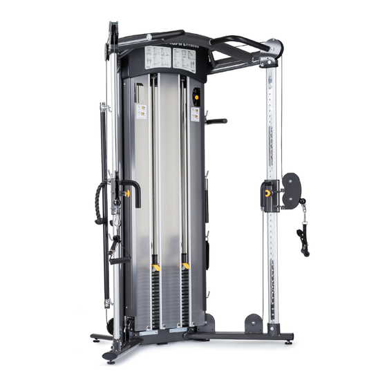
DS972 Functional Trainer
Owner's Manual
Advertisement
Table of Contents

Related Manuals for SPORTS ART DS972


Summary of Contents for SPORTS ART DS972
- Page 1 F: 886 6 3840999 F: +1 425 4888155 T: +44 1509 274440 info@sportsart.com.tw info@gosportsart.com ukinfo@gosportsart.com Sports Art Europe, Middle East & Africa Sports Art China Strada Cantonale 42, Ch-6534 San Vittore, Room 2202, BLDG. A, Huapu Garden, Switzerland Dongzhimen South Street, No. 9,...
- Page 2 DS972 OWNER’S MANUAL CONTENTS 1. INTRODUCTION ................2 2. SAFETY PRECAUTIONS ..............3. LIST OF PARTS ................. 4. ASSEMBLE THE PRODUCT ............. STEP 1 Install the Top Support Frame ........... STEP 2 Install the Support Tube and the Connector ......
-
Page 3: Introduction
1. INTRODUCTION Congratulations on the purchase of a high quality SportsArt product, the DS972 Functional Trainer. Constructed of high quality materials and designed for years of reliable performance, this product was made for full commercial use. Before this product is assembled or operated, we recommend that you familiarize yourself with this manual. -
Page 4: Safety Precautions
2. SAfETy PRECAUTIONS This product was designed and built for optimum safety. However certain precau- tions apply during the use of this product. Please note the following safety precautions: • Please read the entire manual before assembly and operation. Make sure the product is installed and operated as instructed in this manual. -
Page 5: List Of Parts
3. LIST Of PARTS Assembly Parts Name Qty. No. Name Qty. A1 Main frame A7 Rear cover set plate A2 Top support frame A8 Front cover set plate A3 Height adjusting tube A9 Pulley A4 Rear cover A10 Pulley support plate A5 Top rear cover A11 Front cover Left adjustment pulley... - Page 6 Assembly Parts Name Qty. No. Name Qty. Right adjustment pulley A19 Right rear support leg assembly A14 Left connector assembly A20 Hook A15 Right connector assembly 1 A21 Weight stack A16 Front cover set bracket A A22 Weight stack sticker A17 Front cover set bracket B A23 Hardware kit A18 Left rear support leg...
- Page 7 Name Specification Notes Mushroom top inner hex screw M6*P1.0*L12 Spring washer Flat washer D20*d6.3*t1.5 Inner hex screw M8*P1.25*L80 Flat washer D17*d8.3*t2 PU tube ØD12*d8*L61 Nyloc hex lock nut Mushroom top inner hex screw M6*P1.0*L12 Flat washer D13*d6*t1.0 Mushroom top inner hex screw M6*P1.0*L15 Flat washer D13*d6*t1.0...
-
Page 8: Assemble The Product
4. ASSEMBLE THE PRODUCT Follow instructions below to assemble this product. Note that in this manual the words “left” and “right” are used to refer to the product and its parts. As such, these designations correspond to the “left” and “right” sides of a person in position to exercise on this product. -
Page 9: Step 2 Install The Support Tube And The Connector
STEP 2 Install the Support Tube and the Connector (a) Remove screws (31) (40) from the main frame (A1). (b) Attach both connector assembly (A14) (A15) and the rear support legs (A19) (A20) to the main frame (A1). Use screws (31) (40) to secure the whole assembly. - Page 10 STEP 3 Install the Adjustment Pulley and Adjustment Tube (a) First, remove screws (32) from the adjustment tube (A3), and then slide both adjustment pulley assembly (A12) (A13) onto each height adjustment tube (A3). (b) Attach each height adjustment tube (A3) onto the top support frame (A2) and both connector assembly (A14) (A15) at the bottom.
-
Page 11: Step 4 Install The Pulleys
STEP 4 Install the Pulleys (a) Remove screws (33) from the Main Frame (A1). (b) Assemble the pulley assembly with pulley (A9) and pulley plate (A10). Use screws (33) to secure the assembly to the main frame (A1). -
Page 12: Step 5 Install The Weight Plates
STEP 5 Install the Weight Plates... - Page 13 STEP 5 Install the Weight Plates (Continued) (Note: When one side of the weight plates is installed completely, follow the same procedure to install the other side.) (a) Hold the upper stack plate and then cut the zip tie. Gently lower the upper stack plate into place.
- Page 14 STEP 5 Install the Weight Plates (Continued) (d) Insert weight plates (A21) into place on the guide rods one at a time. Once complete, slide down the upper stack carriage on top of the weight stack. (Note: The convex side faces up.) (e) Tilt the guide rods back into place and then lift them up to their mounting position.
-
Page 15: Step 6 Apply The Weight Stack Sticker
STEP 6 Apply the Weight Stack Sticker (a) Align and tape the cardboard to the upper left corner of the weight stack. (b) Peel off the top half of the weight stack sticker (A22) backing. (Note: Leave the clear outside margin in place on the sticker. Don’t peel off the margin.) (c) Align the weight stack sticker (A22) with the right side of the cardboard and the top of the weight stack and then apply the sticker. -
Page 16: Step 7 Install Front Cover Set Brackets
STEP 7 Install front Cover Set Brackets (a) Remove screws (35) from the main frame (A1). (b) Align the holes, use screws (35) to secure the front cover set bracket A (A16) and the front cover set bracket B (A17). (Note: The front cover set brackets are side-specific. - Page 17 STEP 7 Install front Cover Set Brackets (Continued) (c) Remove screws (35) from the bottom of the main frame (A1). (d) Align the holes, use screws (35) to secure the front cover set bracket A (A16) and the front cover set bracket B (A17). (Note: The front cover set brackets are side-specific.
-
Page 18: Step 8 Install Front/Rear Cover Set Plate
STEP 8 Install front/Rear Cover Set Plate (a) Remove screws (36) from the main frame (A1). (b) Place the front cover set plate (A8) and rear cover set plate (A7) outside of the side tabs. Align the holes, use screws (36) to secure the front cover set plate (A8). -
Page 19: Step 9 Install The Cable
STEP 9 Install the Cable (a) Remove screws (37) from the rubber ball on the connector assembly pulleys (A12) (A13) and then pull out the cable. (b) Start from the bottom end of the connector assembly pulleys (A12) (A13) follow the direction of the arrows to install the cable. (Note: Make sure the cable goes through the pulleys). -
Page 20: Step 10 Install The Rear/Front Cover
STEP 10 Install the Rear/front Cover (a) Set the rear cover into the front cover set plate’s groove (A7), and then align holes and fully tighten screws (36) of the rear cover set plate (A7). - Page 21 STEP 10 Install the Rear/front Cover (Continued) (b) Set the front cover (A11) into the front cover set plate’s groove (A8). (c) Align holes and secure 3 pieces of front covers (A11) with screws (12).
-
Page 22: Step 11 Install The Top Front/Rear Cover
STEP 11 Install the Top front/Rear Cover (a) Use screws (13) to secure the top front cover (A6) to the main frame (A1). (b) Press the screw sockets (14) into place on the frame where shown. (c) Use screws (13) to secure the top rear cover (A5) to the main frame (A1). -
Page 23: Step 12 Install The Hooks
STEP 12 Install the Hooks (a) Remove screws (39) from the main frame (A1). (b) Use screws (39) to secure the hooks (A20) onto the main frame (A1). -
Page 24: Step 13 Level And Secure The Product
STEP 13 Level and Secure the Product Follow instructions (a) through (c) below to level and secure the unit. (Note: Adjust the leveler nut at area D first, then area E.) (a) Loosen the leveler nut and then rotate the leveler downward so it firmly touches the floor. -
Page 25: Operate The Product
5. OPERATE THE PRODUCT OPERATION Test the Product (a) Test both pulley handles to confirm they operate correctly. (b) Insert each stack fork to make sure that every weight plate can be engaged easily. - Page 26 OPERATION Test the Product (Continued) (c) Insert each stack fork into the gap under the lowest weight plate. Make sure the gap at area B is between 3~5mm as shown when adjusting. Adjust the nut at area A until the upper stack carriage moves slightly. The gap between the (X) and (Y) nut must be within 35mm(1.4”) and the (X) nut must be secured to a depth of 20mm.
-
Page 27: Operation Operate The Product
OPERATION Operate the Product When the knob is pressed, the actual weight being lifted is configured at a ratio of 2:1. Example: If the stack fork is engaged at 60KG (132LB) at the weight stack, the actual pulling weight is 30KG (66LB). Pull out the knob, the user has a 4:1 ratio and the 60KG (132LB) selected at the weight stack provides an actual pulling weight of 15KG (33LB). -
Page 28: Operation Exercising Instructions
OPERATION Exercising Instructions... - Page 29 OPERATION Exercising Instructions (Continued)
- Page 30 OPERATION Exercising Instructions (Continued)
-
Page 31: Operation Safety Operating Area
OPERATION Safety Operating Area To avoid the unit fall down due to it is quite high, make sure operate it in safety area as shown. (Heavy stack pulley ratio 1:2 99” (252cm) ; Light stack pulley ratio 1:4 118” (300cm).) Safety clearance (600mm) required as below shown. -
Page 32: Maintenance
6. MAINTENANCE This section covers maintenance topics and includes a maintenance sched- ule, task list, and log. MAINTENANCE Safety Precautions ● Please follow standard safety precautions when servicing on this prod- uct. ● Must be performed by trained service personnel only. ●... - Page 33 Maintenance Guide Rod Cleaning and Lubricating 1. Apply lubricant to the guide rods every 3 months. Procedure: (a). Put some lubricant on a clean, lint-free cloth. Rub the lubricated cloth on the guide rods. (b). Load the upper stack carriage set. Exercise to test operation. (c).
- Page 34 MAINTENANCE Schedule Area Week Month Quarter Year Notes Exterior Clean. Inspect for looseness Screws and tighten if necessary. Cable Inspect for wear. Guide rods Clean and lubricate.
-
Page 35: Maintenance Task List
MAINTENANCE Task List Like cars, fitness products require maintenance. Regular maintenance ex- tends product life, and failure to maintain products can void the manufac- turer’s warranty. Copy the maintenance log sheet, and record maintenance work for each fitness product. Daily tasks 1. - Page 36 MAINTENANCE One-year Maintenance Log Facility:_______________________ Supervisor:____________________ Product model number:__________ Serial number:_________________ Start date: ____________________ End date:_____________________ Daily Tasks Weeks 1-7 Weeks 8-14 Weeks 15-21 Week 22-28 Completed Daily Tasks Week 29-35 Week 36-42 Week 43-49 Week 50-52 Completed Weekly Tasks Weeks 1-7 Weeks 8-14 Weeks 15-21 Weeks 22-28...
-
Page 37: Accessories
7. ACCESSORIES ACCESSORIES Options Options Name Qty. No. Name Qty. C1 A93 bench + D handle C3 Optional weight stacks C2 Horn handle... -
Page 38: Consignes De Sécurité Importantes
8. CONSIGNES DE SÉCURITÉ IMPORTANTES Le produit SportsArt a été conçu et fabriqué afin d’assurer une sécurité optimale. Cepen- dant certaines précautions s’appliquent chaque fois que vous utilisez votre produit. • Lisez entièrement le manuel avant l’assemblage et l’utilisation. Veuillez aussi noter les consignes de sécurité... - Page 39 your Authorized Distributor...
Need help?
Do you have a question about the DS972 and is the answer not in the manual?
Questions and answers
I can't locate the serial number of my Sports/art Ds972 functional trainer
The serial number for your Sports Art DS972 Functional Trainer can be found on the product itself. The owner's manual includes a section for recording the serial number, suggesting it is labeled somewhere on the machine. Check the frame or a designated sticker or plate on the unit for the serial number.
This answer is automatically generated