Table of Contents
Advertisement
Quick Links
Download this manual
See also:
User Manual
Advertisement
Table of Contents

Related Manuals for Fluke 6050H


Summary of Contents for Fluke 6050H
- Page 1 Hart Scientific 6050H Calibration Bath User’s Guide Rev. 7B2001...
- Page 2 Limited Warranty & Limitation of Liability Each product from Fluke Corporation, Hart Scientific Division ("Hart") is warranted to be free from de- fects in material and workmanship under normal use and service. The warranty period is one year for the Calibration Bath.
-
Page 3: Table Of Contents
Table of Contents 1 Before You Start ......1 Symbols Used ......1 Safety Information . - Page 4 Bath Tank and Lid ......24 Back Panel......25 8 General Operation .
- Page 5 9.14.1 CTO ........45 9.14.2 CO and CG .
- Page 6 Figures Figure 1 6050H Bath Cross Section (Optional Cart Shown) ... . 9 Figure 2 Tipping Prevention Bracket Installation ....20 Figure 3 Front Panel Features .
- Page 7 Tables Table 1 International Electrical Symbols ..... 1 Table 2 Interface Command Summary ..... . 51 Table 2 Interface Command Summary continued .
-
Page 8: Before You Start
1 Before You Start Symbols Used Before You Start Symbols Used Table 1 lists the International Electrical Symbols. Some or all of these symbols may be used on the instrument or in this manual. Table 1 International Electrical Symbols Symbol Description AC (Alternating Current) AC-DC... -
Page 9: Safety Information
6050H Calibration Bath User’s Guide Symbol Description Canadian Standards Association OVERVOLTAGE (Installation) CATEGORY II, Pollution Degree 2 per IEC1010-1 re- fers to the level of Impulse Withstand Voltage protection provided. Equipment of OVERVOLTAGE CATEGORY II is energy-consuming equipment to be supplied from the fixed installation. - Page 10 1 Before You Start Safety Information control probe may be damaged during shipping and the Service Centers assume no liability for damage incurred during shipping. • DO NOT use the instrument for any application other than calibration work. The instrument was designed for temperature calibration. Any other use of the unit may cause unknown hazards to the user.
- Page 11 6050H Calibration Bath User’s Guide Safety Data Sheet) for the salt used. If you are still unsure if the material you are going to introduce into the bath will react with the salt, refer to the individual MSDS sheets for the three components that make up the salt.
-
Page 12: Cautions
1 Before You Start Safety Information • Keep all combustible materials away from the bath when using salt. Oper- ate the bath on a heatproof surface such as concrete. Provide a means of safety for containing any spill, which may occur. BATH SALT •... -
Page 13: Authorized Service Centers
Authorized Service Centers Please contact one of the following authorized Service Centers to coordinate service on your Hart product: Fluke Corporation, Hart Scientific Division 799 E. Utah Valley Drive American Fork, UT 84003-9775 Phone: +1.801.763.1600 Telefax: +1.801.763.1010... - Page 14 22 Jianguomenwai Dajie Chao Yang District Beijing 100004, PRC CHINA Phone: +86-10-6-512-3436 Telefax: +86-10-6-512-3437 E-mail: xingye.han@fluke.com.cn Fluke South East Asia Pte Ltd. Fluke ASEAN Regional Office Service Center 60 Alexandra Terrace #03-16 The Comtech (Lobby D) 118502 SINGAPORE Phone: +65 6799-5588 Telefax: +65 6799-5588 E-mail: antng@singa.fluke.com...
-
Page 15: Introduction
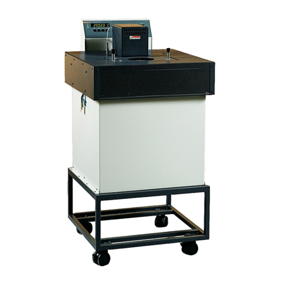
2 Introduction Introduction The Hart Scientific 6050H is a constant temperature bath intended mainly for the application of temperature calibration. However, its high stability and the availability of factory modifications make it suitable for other uses as well. Figure 1 6050H Bath Cross Section (Optional Cart Shown) -
Page 16: Specifications And Environmental Conditions
3 Specifications and Environmental Conditions Specifications Specifications and Environmental Conditions Specifications 6050H Range 180°C to 550°C † Stability ±0.002°C at 200°C (salt) ±0.004°C at 300°C (salt) ±0.008°C at 550°C (salt) ±0.005°C at 200°C (salt) Uniformity ±0.020°C at 550°C (salt) Digital display with push-button data entry Temperature Setting 0.01°C;... - Page 17 6050H Calibration Bath User’s Guide • mains voltage within ± 10% of nominal • vibrations in the calibration environment should be minimized • altitude less than 2,000 meters • indoor use only...
-
Page 18: Quick Start
This section gives a brief summary of the steps required to set up and operate the 6050H bath. This should be used as a general overview and reference and not as a substitute for the remainder of the manual. Please read Section 5 through 8 carefully before operating the bath. -
Page 19: Setting The Temperature
6050H Calibration Bath User’s Guide details. Additionally, a separate ground connection is provided and required to permanently connect the instrument to earth ground for added operator safety. Setting the Temperature In the following discussion and throughout this manual a button icon around the word SET, UP, EXIT or DOWN indicates the panel button while the dotted box indicates the display reading (see Figure 3 on page 23). - Page 20 4 Quick Start Setting the Temperature Return to the temperature display 24.73 C Bath temperature display The bath will heat or cool until it reaches the new set-point temperature. Set the heater switch to position “MED” or “HIGH” to allow the bath to more quickly reach a higher temperature.
-
Page 21: Installation
CAUTION: DO NOT place under a cabinet or other structure. Allow for overhead clearance. The 6050H Bath is a precision instrument which should be located in an appro- priate environment. The location should be free of drafts, extreme temperatures and temperature changes, dirt, etc. The surface where the bath is placed must be level. -
Page 22: Dry-Out" Period
50°C for 4 hours or more. Bath Preparation and Filling The Model 6050H Bath is only intended to be used with salt. Bath salt is avail- able from Hart Scientific and other sources. Bath salt is discussed in detail in Section 8.1.2. -
Page 23: Power
5 Installation Power sensitive. Dropping, striking, or other physical shock may cause a shift in resis- tance in the probe resulting in diminished bath accuracy. If damaged, the probe can be replaced. Contact the factory for assistance. Insert the probe into the inch probe hole at the top left side of the bath lid. -
Page 24: Figure 2 Tipping Prevention Bracket Installation
6050H Calibration Bath User’s Guide ets, please contact an Authorized Service Center (see Section 1.3, Authorized Service Centers). Caster Slots Wall Figure 2 Tipping Prevention Bracket Installation... -
Page 25: Bath Use
General The 6050H bath is intended tob used with heat transfer salt only. Refer to the MSDS (Material Safety Data Sheet) for information specific to the salt se- lected. Generally, baths are set to one temperature and used to calibrate probes only at that single temperature. -
Page 26: Calibration Of Multiple Probes
6050H Calibration Bath User’s Guide the same time. However, stem effect from different types of probes is not to- tally eliminated. Even though all baths have horizontal and vertical gradients, these gradients are minimized inside the bath work area. Nevertheless, probes should be inserted to the same depth in the bath liquid. -
Page 27: Parts And Controls
7 Parts and Controls Front Panel Parts and Controls Front Panel The following controls and indicators are present on the controller front panel (see Figure 3 below): (1) the digital LED display, (2) the control buttons, (3) the bath on/off power switch, (4) the control indicator light, and (5) the heater power switch. -
Page 28: Bath Tank And Lid
6050H Calibration Bath User’s Guide (5) The heater power switch is used to select the appropriate heater power lev- els for heating and controlling temperatures. Bath Tank and Lid The bath tank and lid assembly includes (see Figure 4 on page 24): (1) the tank, (2) the control probe, (3) the stirring motor, (4) the access holes, (5) the access hole cover, and (6) the drain tube. -
Page 29: Back Panel
7 Parts and Controls Back Panel (1) The bath tank is constructed of stainless steel. It is very resistant to oxida- tion in the presence of most chemicals and over a wide range of temperatures. (2) The control probe provides the temperature feedback signal to the controller allowing the controller to maintain a constant temperature. -
Page 30: Figure 5 Back Panel Features
6050H Calibration Bath User’s Guide (4) The control probe plugs into the bath at the socket on the back of the bath labelled “PROBE”. (5) If the bath is supplied with a serial RS-232 interface, the interface cable is attached to the back of the bath at the connector labelled “RS-232”. -
Page 31: General Operation
8 General Operation Bath Fluid General Operation Bath Fluid Heat transfer salt is intended to be used with the 6050H bath. Other fluids should not be used. 8.1.1 Safety Always consider the safety issues associated with using salt in the Warnings and Cautions sections of the Safety Information section (Section 1.2 on page 2) -
Page 32: Stirring
See Section 9.11.2, Stir Mode Se- lect, on page 40. Solid salt has poor thermal conductivity. The 6050H bath uses a special "soft start" program to prevent the heaters from being overheated until the salt is completely molten. -
Page 33: Heater
8 General Operation Heater To turn on the bath switch the control panel power switch to the ON position. The stirring motor will turn on, the LED display will begin to show the bath temperature, and the heater will turn on or off until the bath temperature reaches the programmed set-point. - Page 34 6050H Calibration Bath User’s Guide The bath is operable within the temperature range given in the specifications. For protection against solid-state relay failure or other circuit failure, the mi- cro-controller will automatically turn off the heater with a second mechanical relay anytime the bath temperature is more than a certain amount above the set-point temperature.
-
Page 35: Controller Operation
9 Controller Operation Bath Temperature Controller Operation This chapter discusses in detail how to operate the bath temperature controller using the front control panel. Using the front panel key switches and LED dis- play the user may monitor the bath temperature, set the temperature set-point in degrees C or F, monitor the heater output power, adjust the controller propor- tional band, set the cutout set-point, and program the probe calibration parame- ters, operating parameters, serial and IEEE-488 interface configuration, and... -
Page 36: Figure 6 Controller Operation Flowchart
6050H Calibration Bath User’s Guide Figure 6 Controller Operation Flowchart... -
Page 37: Temperature Set-Point
9 Controller Operation Temperature Set-point The display will indicate the reset function. rESEt ? Cutout reset function Press “SET” once more to reset the cutout. Reset cutout This action also switches the display to the set temperature function. To return to displaying the temperature press the “EXIT”... -
Page 38: Set-Point Value
6050H Calibration Bath User’s Guide Press “SET” to accept the new selection and access the set-point value. Accept selected set-point memory 9.3.2 Set-point Value The set-point value may be adjusted after selecting the set-point memory and pressing “SET”. The set-point value is displayed with the units, C or F, at the left. -
Page 39: Temperature Scale Units
9 Controller Operation Temperature Scale Units Next press “EXIT” to return to the temperature display or “SET” to access the temperature scale units selection. Access scale units Temperature Scale Units The temperature scale units of the controller may be set by the user to degrees Celsius (°C) or Fahrenheit (°F). -
Page 40: Secondary Menu
6050H Calibration Bath User’s Guide Secondary Menu Functions which are used less often are accessed within the secondary menu. The secondary menu is accessed by pressing “SET” and “EXIT” simulta- neously and then releasing. The first function in the secondary menu is the heater power display. -
Page 41: Figure 7 Bath Temperature Fluctuations At Various Proportional Band Settings
9 Controller Operation Proportional Band tional band is too narrow the bath temperature may swing back and forth be- cause the controller overreacts to temperature variations. For best control stability the proportional band must be set for the optimum width. Figure 7 Bath Temperature Fluctuations at Various Proportional Band Settings The optimum proportional band width depends on several factors among which are fluid volume, fluid characteristics (viscosity, specific heat, thermal conduc-... -
Page 42: Cutout
6050H Calibration Bath User’s Guide Access proportional band Proportional band setting Pb=0.101C To change the proportional band press “UP” or “DOWN”. Decrement display Pb=0.060C New proportional band setting To accept the new setting and access the cutout set-point press “SET”. Pressing “EXIT”... -
Page 43: Controller Configuration
9 Controller Operation Controller Configuration Pb=0.101C Proportional band setting Access cutout set-point Cutout set-point CO= 210C To change the cutout set-point press “UP” or “DOWN”. Decrement display CO= 95C New cutout set-point To accept the new cutout set-point press “SET”. Accept cutout set-point The next function is the configuration menu. -
Page 44: Alpha
6050H Calibration Bath User’s Guide 9.10.1 This probe parameter refers to the resistance of the control probe at 0°C. Nor- mally this is set for 100.000 ohms. 9.10.2 ALPHA This probe parameter refers to the average sensitivity of the probe between 0 and 100°C. -
Page 45: Stir Set-Point
9 Controller Operation Operating Parameters Str Act Stir mode selection parameter Press “SET” to access the parameter setting. Stir motor is set for automatic activation at the stir Str=Auto set-point temperature. To change the setting to always on press the “UP” or “DOWN” buttons and then “SET”. -
Page 46: Serial Interface Parameters
6050H Calibration Bath User’s Guide should be set to HIGH enabling all the heaters to provide adequate power to melt the salt and to melt it as quickly as possible. Once the temperature ex- ceeds 200°C, the heaters operate at full power again and the control LED glows red constantly until the set-point temperature is reached. -
Page 47: Sample Period
9 Controller Operation Serial Interface Parameters The BAUD rate of the bath serial communications may be programmed to 300,600,1200, or 2400 BAUD. Use “UP” or “DOWN” to change the BAUD rate value. 2400 b New BAUD rate Press “SET” to set the BAUD rate to the new value or “EXIT” to abort the op- eration and skip to the next parameter in the menu. -
Page 48: Linefeed
6050H Calibration Bath User’s Guide 9.12.4 Linefeed The final parameter in the serial interface menu is the linefeed mode. This pa- rameter enables (on) or disables (off) transmission of a linefeed character (LF, ASCII 10) after transmission of any carriage-return. The linefeed parameter is... -
Page 49: Calibration Parameters
9 Controller Operation Calibration Parameters 9.14 Calibration Parameters The operator of the bath controller has access to a number of the bath calibra- tion constants namely CTO, C0, CG, H, and L. These values are set at the fac- tory and must not be altered. The correct values are important to the accuracy and proper and safe operation of the bath. -
Page 50: H And L
6050H Calibration Bath User’s Guide Press “SET” to show the current value of Cg. Use the “UP and ”DOWN" keys until the value displayed matches the Cg value on the Report of Calibration. Press “SET” to store the value. The display now shows, 9.14.3... -
Page 51: Digital Communication Interface
Serial Communications Digital Communication Interface If supplied with the option, the 6050H bath is capable of communicating with and being controlled by other equipment through the digital interface. Two types of digital interface are available - the RS-232 serial interface and the IEEE-488 GPIB interface. -
Page 52: Baud Rate
6050H Calibration Bath User’s Guide “EXIT” while pressing “SET” and release to enter the secondary menu. Press “SET” repeatedly until the display reads “ProbE”. This is the menu selection. Press “UP” repeatedly until the serial interface menu is indicated with “SE- rIAL”. -
Page 53: Ieee-488 Communication (Optional)
10 Digital Communication Interface IEEE-488 Communication (optional) interface to set the bath and view or program the various parameters. The inter- face commands are discussed in Section 10.3. All commands are ASCII charac- ter strings terminated with a carriage-return character (CR, ASCII 13). 10.2 IEEE-488 Communication (optional) The IEEE-488 interface is available as an option. - Page 54 6050H Calibration Bath User’s Guide the current set-point and, “s=50.00"<CR>, sets the set-point to 50.00 degrees. In the table of commands, characters or data within brackets, “[” and “]”, are optional for the command. A slash, “/”, denotes alternate characters or data.
-
Page 55: Table 2 Interface Command Summary
10 Digital Communication Interface Interface Commands Table 2 Interface Command Summary Command Command Returned Acceptable Command Description Format Example Returned Example Values Display Temperature Read current set-point s[etpoint] set: 9999.99 {C or F} set: 150.00 C Set current set-point to n s[etpoint]=n s=450 Instrument... - Page 56 6050H Calibration Bath User’s Guide Interface Command Summary continued Command Command Returned Acceptable Command Description Format Example Returned Example Values Set cutout to be reset cm[ode]=a[uto] cm=a automatically Read stirrer mode smod smod smod:{xxxx} smod:AUTO ON or AUTO Set stirrer mode:...
-
Page 57: Power Control Functions
To allow the interface to control the heating, the front panel controls are dis- abled by switching the heater switch to “LOW”. Otherwise, the interface would not be able to switch the heater functions off. The 6050H bath has two control functions with the digital interface. These control functions are for heaters set- tings Med and High. -
Page 58: Calibration Procedure
11 Calibration Procedure Calibration Points Calibration Procedure NOTE: This procedure is to be considered a general guideline. Each lab- oratory should write their own procedure based on their equipment and their quality program. Each procedure should be accompanied by an un- certainty analysis also based on the laboratory's equipment and environ- ment. -
Page 59: Computing R0 And Alpha
6050H Calibration Bath User’s Guide was set for 150°C and the thermometer measured 150.1°C giving an error of +0.1°C. 11.3 Computing R0 and ALPHA Before computing the new values for R0 and ALPHA, the current values must be known. The values may be found by either accessing the probe calibration menu from the controller panel or by inquiring through the digital interface. -
Page 60: Figure 9 Calibration Example
11 Calibration Procedure Calibration Example R0 = 100.000 ALPHA = 0.0038500 = 80.00°C measured t = 79.843°C = 120.00°C measured t = 119.914°C Compute errors, = 79.843 - 80.00°C = -0.157°C = 119.914 - 120.00°C = -0.086°C Compute R − −... -
Page 61: Maintenance
12 Maintenance Maintenance The calibration instrument has been designed with the utmost care. Ease of op- eration and simplicity of maintenance have been a central theme in the product development. Therefore, with proper care the instrument should require very little maintenance. Avoid operating the instrument in dirty or dusty environments. - Page 62 6050H Calibration Bath User’s Guide • If the instrument is used in a manner not in accordance with the equip- ment design, the operation of the bath may be impaired or safety hazards may arise. NOTE: When checking the over-temperature cutout, be sure that the tem- perature limits of the bath fluid are not exceeded.
-
Page 63: Troubleshooting
13 Troubleshooting Troubleshooting Troubleshooting In the event the bath appears to function abnormally this section may help to find and solve the problem. Several possible problem conditions are described along with likely causes and solutions. If a problem arises please read this sec- tion carefully and attempt to understand and solve the problem. - Page 64 6050H Calibration Bath User’s Guide Problem Causes and Solutions The display flashes Low battery. A problem could exist with the memory back-up battery. If the bat- “CUToUT” alternately tery voltage is insufficient to maintain the memory, data may become scrambled with an incorrect process causing problems.
-
Page 65: Comments
13 Troubleshooting Comments Problem Causes and Solutions Stir motor does not Improper setting or normal operation. See Section 9.11.2, Stir Mode Select, for function proper stir mode settings. NOTE: Stir Mode Select defaults to “Auto” each time the power of the bath is cycled off and back on.
Need help?
Do you have a question about the 6050H and is the answer not in the manual?
Questions and answers