Table of Contents
Advertisement
Quick Links
MODEL T10814
TOOL GRINDER
w/CUP GRINDING WHEEL
OWNER'S MANUAL
(For models manufactured since 5/15)
COPYRIGHT © JULY, 2014 BY GRIZZLY INDUSTRIAL, INC. REVISED JULY, 2017 (JH)
WARNING: NO PORTION OF THIS MANUAL MAY BE REPRODUCED IN ANY SHAPE
OR FORM WITHOUT THE WRITTEN APPROVAL OF GRIZZLY INDUSTRIAL, INC.
#MNTSDM16565 PRINTED IN CHINA
V2.07.17
Advertisement
Table of Contents

Related Manuals for Grizzly T10814


Summary of Contents for Grizzly T10814
- Page 1 OWNER'S MANUAL (For models manufactured since 5/15) COPYRIGHT © JULY, 2014 BY GRIZZLY INDUSTRIAL, INC. REVISED JULY, 2017 (JH) WARNING: NO PORTION OF THIS MANUAL MAY BE REPRODUCED IN ANY SHAPE OR FORM WITHOUT THE WRITTEN APPROVAL OF GRIZZLY INDUSTRIAL, INC.
- Page 2 This manual provides critical safety instructions on the proper setup, operation, maintenance, and service of this machine/tool. Save this document, refer to it often, and use it to instruct other operators. Failure to read, understand and follow the instructions in this manual may result in fire or serious personal injury—including amputation, electrocution, or death.
-
Page 3: Table Of Contents
Belt Tension & Replacement ....... 32 SECTION 2: POWER SUPPLY ...... 11 SECTION 8: WIRING ........33 SECTION 3: SETUP ........13 Wiring Safety Instructions ......33 T10814 Wiring..........34 Needed for Setup ......... 13 Unpacking ............ 13 Wiring Photos..........35 Inventory ............14 SECTION 9: PARTS ........ -
Page 4: Introduction
INTRODUCTION Machine Description Manual Accuracy We are proud to provide a high-quality owner’s The Model T10814 Tool Grinder is designed for manual with your new machine! sharpening or grinding HSS and carbide cutting tools, including both single- and multiple-lip cut- We made every effort to be exact with the instruc- ters. -
Page 5: Identification
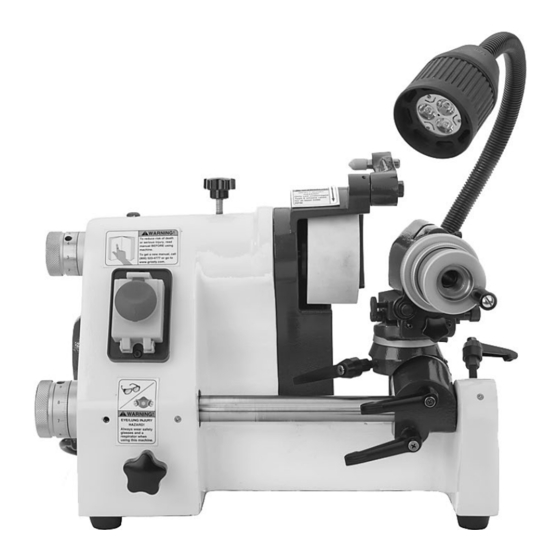
Lock Lever Dial Guide Rod Guide Rod Index Bracket Micro-Adjust Knob Lock Levers Figure 1. Model T10814 names and locations of controls and features. To reduce your risk of serious injury, read this entire manual BEFORE using machine. Model T10814 (Mfd. Since 5/15) -
Page 6: Controls & Components
B. Guide Rod Micro-Adjust Knob: Rotates the guide rod toward and away from the grinding wheel to control rate of feed during opera- tions. C. Guide Rod Lock Lever: Locks the guide rod in place for greater accuracy during opera- tions. Model T10814 (Mfd. Since 5/15) - Page 7 Carriage Slide Adjustment Knob: Moves the tool holder left and right, relative to the grinding wheel. K. Cross Slide Gib Lock Knob: Locks the cross slide in place. Carriage Slide Gib Lock Knob: Locks the carriage slide in place. Model T10814 (Mfd. Since 5/15)
- Page 8 Horsepower ................................⁄ Voltage ..................................110V Phase ................................Single-Phase Amps .................................... 3A Speed ................................3450 RPM Cycle ..................................60 Hz Power Transfer ..............................Round Belt Bearings ........................Shielded and Permanently Sealed Model T10814 (Mfd. Since 5/15) Model T10814 Page 1 of 2...
- Page 9 CSA Certified ..................................No Features: Micrometer dial for depth adjustment Built-in wheel dresser Halogen work light Accessories: Aluminum-oxide grinding wheel for HSS 5 collets (1/8", 1/4", 3/8", 1/2", 5/8") Service tools Model T10814 (Mfd. Since 5/15) Page 2 of 2 Model T10814...
-
Page 10: Section 1: Safety
Everyday ery. Never operate under the influence of drugs or eyeglasses are NOT approved safety glasses. alcohol, when tired, or when distracted. Model T10814 (Mfd. Since 5/15) - Page 11 EXPERIENCING DIFFICULTIES. If at any time debris. Make sure they are properly installed, you experience difficulties performing the intend- undamaged, and working correctly BEFORE ed operation, stop using the machine! Contact our operating machine. Technical Support at (570) 546-9663. Model T10814 (Mfd. Since 5/15)
-
Page 12: Additional Safety For Tool Grinders
Perform routine inspections and all necessary grinding. maintenance, as indicated in owner’s manual. Never operate machine with damaged or worn parts that can break during operation. -10- Model T10814 (Mfd. Since 5/15) -
Page 13: Section 2: Power Supply
-11- Model T10814 (Mfd. Since 5/15) -
Page 14: Extension Cords
Two-prong outlets do not meet the grounding requirements for this machine. Do not modify or use an adapter on the plug provided—if it will not fit the outlet, have a qualified electrician install the proper outlet with a verified ground. -12- Model T10814 (Mfd. Since 5/15) -
Page 15: Section 3: Setup
When you are completely satisfied with the condi- tion of your shipment, inventory the contents. SUFFOCATION HAZARD! Keep children and pets away from plastic bags or packing materials shipped with this machine. Discard immediately. -13- Model T10814 (Mfd. Since 5/15) -
Page 16: Inventory
NOTICE Figure 6. Small item inventory. Avoid chlorine-based solvents, such as acetone or brake parts cleaner, that may damage painted surfaces. -14- Model T10814 (Mfd. Since 5/15) -
Page 17: Site Considerations
Page 28 for specific details. Children and visitors may be seriously injured if unsuper- vised around this machine. Lock entrances to the shop or disable start switch or power connection to prevent unsupervised use. -15- Model T10814 (Mfd. Since 5/15) -
Page 18: Test Run
Turn machine ON by pressing green ON button. Allow wheel to reach full speed and rotate for at least one minute, then turn OFF. The motor should run smoothly and without unusual problems or noises. -16- Model T10814 (Mfd. Since 5/15) -
Page 19: Section 4: Operations
Read books/magazines or get formal training before beginning any proj- ects. Regardless of the content in this sec- tion, Grizzly Industrial will not be held liable for accidents caused by lack of training. -17- Model T10814 (Mfd. Since 5/15) -
Page 20: Wheel Care
Wheel Care Wheel Selection The Model T10814 accepts Type 6 grinding When grinding, your safety depends, to a large wheels with a 20mm bore. Included with the tool degree, on the condition of the wheel. A wheel in grinder is an aluminum-oxide wheel for grinding poor condition presents the possibility of breaking HSS. -
Page 21: Wheel Inspection
Balance wheel with your finger in hole. If this is not possible, hang the wheel in the air with a piece of cord or string looped through hole in center. -19- Model T10814 (Mfd. Since 5/15) -
Page 22: Installing/Removing Wheel
Remove screwdriver from spindle lock access hole, and re-install cap screw. Note: If grinding wheel is new, refer to Truing/Dressing Wheel on Page 21 for fur- ther instructions. -20- Model T10814 (Mfd. Since 5/15) -
Page 23: Truing/Dressing Wheel
Set Screw tory illness. Reduce your risk by wearing a respirator and capturing the dust with a Figure 12. Dressing tool positioned against face dust collection system. of grinding wheel for truing (or dressing). -21- Model T10814 (Mfd. Since 5/15) -
Page 24: Moving Tool Bracket
The horizontal mount tilts left to right from 0˚–45˚ and includes an embedded degree scale. The lateral mount twists side-to-side, relative to the spindle, and includes an adjustable degree scale. -22- Model T10814 (Mfd. Since 5/15) -
Page 25: Tool Holder
Twist lock ring to left until index ring moves freely and does not engage quill. Carriage Gib Lock Twist index ring to desired position. Cross Slide Gib Lock Figure 17. Locations of cross slide and carriage Retighten lock ring. controls. -23- Model T10814 (Mfd. Since 5/15) -
Page 26: Installing/Removing Tooling
Installing/Removing Note: Interior of quill has an alignment pin that must be aligned with slot in collet (see Tooling Figure 20). The Model T10814 Tool Grinder comes with five Alignment Slot collets ( ⁄ ", ⁄ ", ⁄ " ⁄... -
Page 27: Spindle Controls
To adjust spindle: Ensure tool holder is clear of grinding wheel to avoid accidental contact. Loosen spindle lock knob (see Figure 21). Lock Knob Spindle Dial Figure 21. Locations of spindle dial and lock knob. -25- Model T10814 (Mfd. Since 5/15) -
Page 28: Section 5: Accessories
5 ounces of oil. T26602—Replacement Diamond Wheel for the T10814 Designed for grinding carbide steel, this grinding wheel is a precise fit for the T10814 Tool Grinder. H7616 H7617 Figure 22. High-pressure oil cans for ball oilers. Replacement Collets for the T10814 Figure 24. - Page 29 Won’t gum up! 1/2" stepped shank. Comes in a wooden case. 12 oz. AMGA#2 (ISO 68 Equivalent). Figure 26. H7695 Giant Brad Point Bit Set. Figure 28. SB1365 Way Oil. -27- Model T10814 (Mfd. Since 5/15)
-
Page 30: Section 6: Maintenance
Before performing lubrication task, DISCONNECT TOOL GRINDER FROM POWER! Items Needed Clean Rag ........As Needed Mineral Spirits ........As Needed Stiff Brush ............1 Pump-Type Oil Can w/Plastic Cone Tip .... 1 -28- Model T10814 (Mfd. Since 5/15) - Page 31 Figure 30. Location of cross slide and carriage Refer to Figure 29 for the location of the ball oil- slide. ers on this machine. Ball Oilers Figure 29. Location of ball oilers. -29- Model T10814 (Mfd. Since 5/15)
-
Page 32: Section 7: Service
2. Grinding wheel loaded up. 2. Dress grinding wheel (see Truing/Dressing Wheel quickly. on Page 21); replace grinding wheel. 3. Grinding wheel stored in damp 3. Replace grinding wheel; store wheels in cool, dry environment. area. -30- Model T10814 (Mfd. Since 5/15) -
Page 33: Gib Adjustment
(see Figures 31–32). When satisfied with gib adjustment, use hex wrench to prevent gib screws from moving, then retighten hex nuts to secure settings. Recheck movement of slide and, if neces- sary, repeat Steps 2–4. -31- Model T10814 (Mfd. Since 5/15) -
Page 34: Belt Tension & Replacement
Insert new belt in motor pulley, then pull onto Pulley drive pulley. This belt stretches easily and will slip into place. Figure 35. Correct timing-belt deflection. Tension the belt (see Tensioning Belt for Re-install belt cover. detailed instructions). Re-install belt cover. -32- Model T10814 (Mfd. Since 5/15) -
Page 35: Section 8: Wiring
Technical source. Support at (570) 546-9663. The photos and diagrams included in this section are best viewed in color. You can view these pages in color at www.grizzly.com. -33- Model T10814 (Mfd. Since 5/15) -
Page 36: T10814 Wiring
ON/OFF Switch DKLD LDZ-6-2 LED Driver Model: 1W-3W INPUT: 85-265V 50/60Hz Capacitor OUTPUT: DC2-12V/300MA 25MFD 450VAC TB-1504L Induction Motor 1/4 HP Work Lamp (viewed from bottom of machine) Neutral 110 VAC 5-15 Plug Ground -34- Model T10814 (Mfd. Since 5/15) -
Page 37: Wiring Photos
Wiring Photos Figure 36. Wiring components viewed from below machine. Figure 37. ON/OFF switch. Figure 38. Work lamp. READ ELECTRICAL SAFETY -35- Model T10814 (Mfd. Since 1/14) ON PAGE 33! -
Page 38: Section 9: Parts
Please Note: We do our best to stock replacement parts whenever possible, but we cannot guarantee that all parts shown here are available for purchase. Call (800) 523-4777 or visit our online parts store at www.grizzly.com to check for availability. -
Page 39: Main Parts List
Safety labels help reduce the risk of serious injury caused by machine hazards. If any label comes off or becomes unreadable, the owner of this machine MUST replace it in the original location before resuming operations. For replacements, contact (800) 523-4777 or www.grizzly.com. -37-... - Page 40 -38- Model T10814 (Mfd. Since 5/15)
- Page 41 Would you recommend Grizzly Industrial to a friend? _____ Yes _____No Would you allow us to use your name as a reference for Grizzly customers in your area? Note: We never use names more than 3 times. _____ Yes _____No 10.
- Page 42 FOLD ALONG DOTTED LINE Place Stamp Here GRIZZLY INDUSTRIAL, INC. P.O. BOX 2069 BELLINGHAM, WA 98227-2069 FOLD ALONG DOTTED LINE Send a Grizzly Catalog to a friend: Name_______________________________ Street_______________________________ City______________State______Zip______ TAPE ALONG EDGES--PLEASE DO NOT STAPLE...
-
Page 43: Warranty & Returns
WARRANTY & RETURNS Grizzly Industrial, Inc. warrants every product it sells for a period of 1 year to the original purchaser from the date of purchase. This warranty does not apply to defects due directly or indirectly to misuse, abuse, negligence, accidents, repairs or alterations or lack of maintenance.
Need help?
Do you have a question about the T10814 and is the answer not in the manual?
Questions and answers