Table of Contents
Advertisement
Quick Links
Advertisement
Table of Contents

Related Manuals for Insportline 16148


Summary of Contents for Insportline 16148
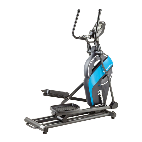
- Page 1 USER MANUAL – EN IN 16148 Elliptical Cross Trainer inSPORTline Oregon...
-
Page 2: Table Of Contents
CONTENTS SAFETY PRECAUTIONS ........................3 HARDWARE LIST ..........................4 PARTS LIST ............................4 EXPLODED DRAWINGS ........................8 ASSEMBLY INSTRUCTIONS ......................10 FOOT PAD INSTALLATION ....................10 MAIN FRAME INSTALLATION ....................10 HANDRAIL AND SLIDING TUBE INSTALLATION ..............11 LEFT/RIGHT FOOT PEDAL INSTALLATION ................. 12 LEFT/RIGHT HANDRAIL INSTALLATION ................ -
Page 3: Safety Precautions
SAFETY PRECAUTIONS • Read this manual carefully before first using and retain it for future reference. Observe all warnings and precautions and use it only for intended purpose. • Read all instructions carefully. Use this device only according to this manual. Don’t do any improper modification of this product. -
Page 4: Hardware List
HARDWARE LIST Picture Description Qty. Bolt M6*15 Washer ø6*ø12*1.0 Self-tapping drilling screw ST4.2*20 Self-tapping screw ST4.2*20 Self-tapping screw ST2.9*16 Hexagon bolt M8-40 Hexagon lock nut M8 Bolt M8*55 Washer ø8*ø20*2.0 Hexagon lock nut M8 Allen wrench S6 Allen wrench S5 Multi-hex tool with Phillips screwdriver S10-13-14-15 Dull-head wrench PARTS LIST... - Page 5 Big washer ø8*ø25*2.0 Bushing ø33*ø19*31 Bushing ø50*ø26*31 Hexagon lock nut M8 Hexagon bolt M8-40 Self-tapping drilling screw ST4.2*20 Self-tapping screw ST2.9*16 Left handrail arm cover A Left handrail arm cover B Right handrail arm cover A Right handrail arm cover B Handlebar foam grip ø32 End cap for handlebar Self-tapping screw ST4.2*20...
- Page 6 End cap for handlebar Handlebar foam grip ø28 Hand pulse sensor with wire Meter Right foot tube cover A Right foot tube cover B Nut M10 Foot pad Screw M5*10 Curve washer ø8 Flange nut M10*1.25 Left crank Cover for crank Left chain cover Circlip Tension cable (L 1600 mm)
- Page 7 Transport wheel Bolt M6x12 Left foot pad Screw ST2.9x10 Right foot pad Tension control knob Screw M5x12 Washer ø5 End cap for ellipse tube Right foot pedal Sliding tube cover Taper Washer Ø11.8x Ø 8x5 Fixed tube Plastic stub End cap Aluminum sheet Screw Bottle Holder...
-
Page 8: Exploded Drawings
EXPLODED DRAWINGS... -
Page 10: Assembly Instructions
ASSEMBLY INSTRUCTIONS 1. FOOT PAD INSTALLATION • Attach four-foot pads (57) onto rear main frame (2). 2. MAIN FRAME INSTALLATION • Remove two Bolt M8*20 (10) from the Fixed tube (100). Remove the Fixed tube (100) from the Main Frame (1). •... -
Page 11: Handrail And Sliding Tube Installation
3. HANDRAIL AND SLIDING TUBE INSTALLATION • Remove one bolt M8x20 (10), one spring washer ø8 (11), one flat washer ø8xø25*2.0 (12) from the left horizontal axes of the main frame (1). • Attach left handrail (5) onto left horizontal axis of the main frame (1) with one bolt M8x20 (10), one spring washer ø8 (11), one flat washer ø8xø25*2.0 (12) that have been removed. -
Page 12: Left/Right Foot Pedal Installation
4. LEFT/RIGHT FOOT PEDAL INSTALLATION • Attach left foot pedal (32) onto left foot pedal tube (6) using four bolts M6*15 (33), four washers ø6*ø12*1.0 (34). • Attach right foot pedal (97) onto right foot pedal tube (7) using four bolts M6*15 (33), four washers ø6*ø12*1.0 (34). -
Page 13: Handlebar Installation
6. HANDLEBAR INSTALLATION • Remove one bolt M8x20 (10) and one curve washer ø8 (59) from handlebar (9). • Insert hand pulse sensor wires (52) from the handlebar (9) into the hole on the front post of the main frame (1) and pull them out from the top end of the main-frame front post (1). •... -
Page 14: Handrail Arm Cover/Foot Tube Cover/Sliding Tube Cover
8. HANDRAIL ARM COVER/FOOT TUBE COVER/SLIDING TUBE COVER • Attach left handrail arm cover A/B (19/20) onto left handrail arm (3) with two self-tapping screws ST2.9*16 (18) and two self-tapping drilling screws ST4.2*20 (17). • Attach right handrail arm cover A/B (21/22) onto right handrail arm (4) with two self-tapping screws ST2.9*16 (18) and two self-tapping drilling screws ST4.2*20 (17). -
Page 15: Bottle Holder Instalation
9. BOTTLE HOLDER INSTALATION Attach the Bottle Holder (105) onto the main fame with two Screw ST4.8*15(106). Attach the Bottle (107) onto the Bottle Holder (105). NOTE: Grease the aluminum rods. -
Page 16: Computer Instruction Manual
COMPUTER INSTRUCTION MANUAL FUNCTION RANGE 00:00 – 99:59 TIME 0.0 – 99.9 km/h (mph) SPEED (SPD) 0.00 – 9999 km (ml) DISTANCE 0.0 – 9999 kcal BURNED CALORIES 0.0 – 9999 km (ml) ODOMETER (ODO) 0 - 9999 PULSE (PUL) 0, 40~240 bpm KEY FUNCTIONS MODE... -
Page 17: Functions
MODE key until pointer starts blinking on required function. FUNCTIONS TIME Push MODE key until pointer locks on the TIME. After starting a workout, total working time will be displayed. SPEED Push MODE key until pointer advances to SPEED to show current speed. -
Page 18: Exercise Instructions
• Never catch and hold sensors too firmly. Only moderate pressure is required. Squeaking and unusual noises. Check all bolts if they are not loose. Retighten if necessary. EXERCISE INSTRUCTIONS Each workout should consist of following three phases: warm-up phase, aerobic phase, cool-down phase. -
Page 19: Aerobic Phase
Calves and Achilles tendon Lean against a wall with your left leg in front of the right and have your arms stretched forwards. Keep your right leg straight and let your left foot staying on the floor. Bend your left leg and lean forward by moving your hips toward the wall. - Page 20 Warranty & Service Centre: Cermenska 486, 749 01 Vitkov, Czech Republic CRN: 26847264 VAT ID: CZ26847264 Phone: +420 556 300 970 E-mail: eshop@insportline.cz reklamace@insportline.cz servis@insportline.cz Web: www.insportline.cz INSPORTLINE s.r.o. Headquarters, Warranty & Service centre: Elektricna 6471, 911 01 Trencin, Slovakia...
- Page 21 CRN: 36311723 VAT ID: SK2020177082 Phone: +421(0)326 526 701 E-mail: objednavky@insportline.sk reklamacie@insportline.sk servis@insportline.sk Web: www.insportline.sk Date of Sale: Stamp and Signature of Seller:...
Need help?
Do you have a question about the 16148 and is the answer not in the manual?
Questions and answers