Table of Contents
Advertisement
Quick Links
Advertisement
Table of Contents

Related Manuals for Insportline 13902


Summary of Contents for Insportline 13902
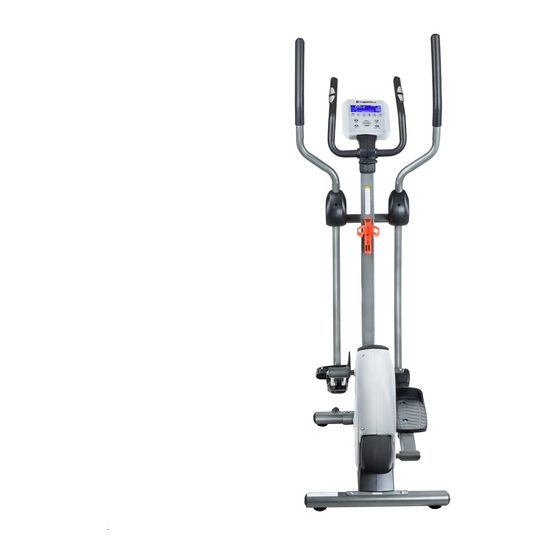
- Page 1 USER MANUAL – EN IN 13902 Elliptical Trainer inSPORTline Kalida...
-
Page 2: Table Of Contents
CONTENTS SAFETY INSTRUCTIONS ........................3 PARAMETERS ............................4 ASSEMBLY ............................. 4 Assembly hardware ..........................4 Tools ..............................5 Assembly drawing ..........................7 Assembly steps ............................ 8 CONTROL PANEL ..........................12 Display function ..........................12 Key functions............................13 Operations............................13 GENERAL FITNESS TIPS ........................17 Warm-up/stretching exercises ...................... -
Page 3: Safety Instructions
SAFETY INSTRUCTIONS Make sure you read the entire manual before using the product for the first time. Keep the manual for future reference. WARNING: This elliptical trainer has been designed and constructed to provide maximum safety. Nevertheless, certain precautions should be taken when using it. Observe the following safety precautions. -
Page 4: Parameters
Weight limit: 120 kg Category: HC (EN 957) for home use only WARNING! The heart rate frequency monitoring may not be completely accurate. Overexertion during training can lead to a serious injury or even death. If you start to feel faint, stop the exercise immediately. -
Page 5: Tools
M4×10 Philips C.K.S. full thread screw Assembly hardware table: Tools Description Specification Allen Key 5 x 80 x 80S Allen Key 5 x 35 x 85S Allen Key 6 x 40 x 120 Cross spanner #15 + #17 Open cross spanner Gather the necessary tools before the assembly. - Page 6 space to properly assemble the unit. Make sure the space is free of anything that may cause you injury during assembly. After the unit is fully assembled, secure a comfortable amount of free area around the machine for unobstructed operation. NOTE: Each step of the assembly instructions describes what to do.
-
Page 7: Assembly Drawing
Assembly drawing... -
Page 8: Assembly Steps
Assembly steps STEP 1 Attach the front stabilizer (2) to the main frame (1) with flat washers (33), spring washers (32) and Allen C.K.S. half thread screws (31). STEP 2 Attach the rear stabilizer (3) to the main frame (1) with flat washers (33), spring washers (32) and Allen C.K.S. - Page 9 TIP: Put the communication wires and resistance adjust knob wire into the upright post and make sure all screws are in the hexagonal hole before tightening all bolts. STEP 4 Attach the wave spring washer (39) to the axle (15), then attach the body arm set (5) to the axle (15) and tighten it with flat washer (33) and Allen C.K.S.
- Page 10 3. Attach the right body arm the same way. TIP: Make sure all screws are in the hexagonal hole before tightening all bolts. STEP 6 1. Attach the left pedal (13) to the pedal supporter (8) with carriage screws (41), flat washers (42) and knobs (93).
- Page 11 3. Attach the body arm covers (19, 20) to the pedal supporter (8) with a Philips C.K.S. self- tapping screw (38). 4. Install the right pedal supporter (14) the same way. STEP 8 1. Pull the handle pulse connection wire (28) through the upright post (4) and attach the Handlebars (9) to the upright post (4) with the T-shaped rotary knob (21).
-
Page 12: Control Panel
3. Attach the left handlebar cover (22) and the right handlebar cover (23) through the handlebars (9) to the upright post (4) with Philips C.K.S. full head screws (48). TIP: Make sure all screws are in the hexagonal hole before tightening all bolts. NOTE: Adjust the handlebars (9) correctly, in a 100 mm distance from the console (11). -
Page 13: Key Functions
Displays the numerical value of user’s pulse during PULSE exercise. The device will alert you, if you exceed the preset target heart rate frequency. Displays the numerical value of rotations per minute during exercise. Range: 0 – 999 rpm WATTS Displays the consumed power rate during the exercise. - Page 14 MANUAL MODE Press START/STOP to directly enter the manual setting mode. 1. Press UP and DOWN to select a program, select MANUAL and press MODE to confirm. 2. Set the values for TIME, DISTANCE, CALORIES and PULSE. Press MODE to confirm. 3.
- Page 15 5. Press START/STOP again to pause the exercise. If you press the RESET key, you’ll return to the main display. USER PROGRAM 1. Press the UP and DOWN keys to select a program, select USER PROGRAM and press MODE to confirm. 2.
- Page 16 5. You can press the UP and DOWN keys to adjust the WATT value during exercising. HEART RATE RECOVERY STATUS 1. After exercising for a period of time, hold the hand grips and press the RECOVERY key. 2. All display functions will stop, except for TIME, which will start to count down 60 seconds. 3.
-
Page 17: General Fitness Tips
GENERAL FITNESS TIPS Start your exercise program slowly, i.e. one exercise unit every 2 days. Increase your exercise sessions week by week. Begin with short periods per exercise and then increase these continually. Start slowly and don’t set yourself impossible targets. In addition to these exercises do other forms of exercise, such as jogging, swimming, dancing and/or cycling. - Page 18 ARM STRETCHING EXERCISES Stretch the left and right arms alternately towards the ceiling. Feel the tension in your left and right side. Repeat this exercise several times. EXERCISES FOR THE UPPER THIGH Support yourself by placing your hand on the wall, then reach down behind you and lift up your right or left foot as close to your buttocks as possible.
- Page 19 EXERCISES FOR THE KNEES Sit on the floor and stretch out your right leg. Bend your left leg and place your foot on your upper thigh. Now try to reach your right foot with your right arm. Maintain this position for 30 – 40 seconds if possible.
-
Page 20: Exploded Drawing
EXPLODED DRAWING... -
Page 21: Parts List
PARTS LIST NAME SPECIFICATION Main frame Front stabilizer... - Page 22 Rear stabilizer Upright post Saddle post Body arm (L) Body arm (R) Pedal supporter (L/R) Handlebars Console fixed piece Console Bottle holder Pedal (L) Pedal (R) Φ15×311.5 Axle Bottom stand post cover Body Arm cover 1 (Upper) Body Arm cover 2 (Upper) Body Arm cover 1 (Bottom) Body Arm cover 2 (Bottom) M8×30...
- Page 23 M10×50×20 carriage screw Φ10 Flat washer Hex locking nut Φ10×56.5-M6×20 Allen C.K.S. hollow screw Φ6 Flat washer M6×15 Allen C.K.S. full thread screw M5×10 Philips C.K.S. full head screw M4×10 Philips C.K.S. full head screw M5×10(black) Philips C.K.S. full head screw Power adapter Motor Φ38×15.4...
-
Page 24: Terms And Conditions Of Warranty, Warranty Claims
Magnetic induction block ST4×12 Philips C.K.S. self-tapping screw Brake tension spring Φ30×t3.0×350 Foam grip Φ32×t1.5 Pipe plug Deep groove ball bearing 6002-2RS Deep groove ball bearing 6000-2RS Motor cover (L) Motor cover (R) Tension pulley Upright post decoration strip ST4×25 Philips C.K.S. - Page 25 Borivojova 35/878, 130 00 Praha 3, Czech Republic Headquarters: Delnicka 957, 749 01 Vitkov, Czech Republic Warranty & Service Centre: Cermenska 486, 749 01 Vitkov, Czech Republic CRN: 26847264 VAT ID: CZ26847264 Phone: +420 556 300 970 E-mail: eshop@insportline.cz reklamace@insportline.cz servis@insportline.cz...
- Page 26 Web: www.insportline.cz INSPORTLINE s.r.o. Headquarters, Warranty & Service centre: Elektricna 6471, 911 01 Trencin, Slovakia CRN: 36311723 VAT ID: SK2020177082 Phone: +421(0)326 526 701 E-mail: objednavky@insportline.sk reklamacie@insportline.sk servis@insportline.sk Web: www.insportline.sk Date of Sale: Stamp and Signature of Seller:...
Need help?
Do you have a question about the 13902 and is the answer not in the manual?
Questions and answers