
Related Manuals for Kentec Electronics Sigma XT Plus


Summary of Contents for Kentec Electronics Sigma XT Plus
- Page 1 Sigma XT+ Extinguishant Control Panel Operation and Maintenance Manual Man-1112 Issue 23 March 2016...
-
Page 2: Table Of Contents
Index Contents Introduction ..................5 2. Safety and mounting ................. 6 2.1 Safety ....................6 2.2 Mounting ..................7 3. Technical specification ............... 8 4. Control panel fascias ................ 12 4.1 Removing the fire detection equipment chassis ......... 13 5. - Page 3 15.2.12 Delay on manual release ................32 15.2.13 Release timer (infinite extinguishant duration) ..........32 15.2.14 R0V not removed on reset ................. 33 15.2.15Disable earth fault monitoring ..............33 15.2.16 Disable fault output .................. 33 15.2.17 Invert low pressure switch input ..............
- Page 4 18.1.4 Aux 24V fault .................... 41 18.1.5 Batt low ....................41 18.1.6 Comms fault ..................... 42 18.1.7 Earth fault ....................42 18.1.8 Sys fuse fault .................... 42 18.1.9 S1 fault ....................42 18.1.10 S2 fault ....................42 ...
-
Page 5: Introduction
Introduction The SIGMA XT+ range of control panels are designed in accordance with European standards EN54-2 and EN54-4 Fire Detection and Fire Alarm systems - Control and Indicating Equipment and EN12094-1 Fixed firefighting systems - Components for gas extinguishing systems - Part 1: Requirements and test methods for electrical automatic control and delay devices. -
Page 6: Safety And Mounting
2. Safety and mounting 2.1 Safety Suppliers of articles for use at work are required under section 6 of the Health and Safety at Work act 1974 to ensure as reasonably as is practical that the article will be safe and without risk to health when properly used. An article is not regarded as properly used if it is used ‘without regard to any relevant information or advice’... -
Page 7: Mounting
2.2 Mounting The control panel should be mounted on a dry, flat surface, at eye height to the displays and in a level position such that the enclosure is not distorted. Screws or bolts of a minimum of 5mm diameter must be used to mount the enclosure in all four mounting positions. It should be positioned in an accessible place as agreed with the end user. -
Page 8: Technical Specification
3. Technical specification Table 1 - Electrical specifications ITEM ELECTRICAL RATING COMMENT COMMUNICATION PARAMETERS Mains supply 230V AC, 50Hz +10% - 15% (100 Watts maximum) Standard European mains connection Mains supply fuse (K21021, 1.6 Amp ( F1.6A L250V) Replace only with similar type K21041, K21042, K21081, K21082) Mains supply fuse (K21083,... - Page 9 Local fire relay contact rating 5 to 30VDC 1A Amp maximum for each Maximum ratings not to be exceeded Volt free changeover contact First stage contact rating 5 to 30VDC 1A Amp maximum for each Maximum ratings not to be exceeded Volt free changeover contact Second stage contact rating 5 to 30VDC 1A Amp maximum for each...
- Page 10 Table 2 - Compatible detectors Model Type Manufacturer Maximum Number per zone SLR-E/SLR-E3 OPTICAL Hochiki SIJ-E/ IONISATION Hochiki DCD-1E/DCD-AE3 HEAT Hochiki DCD-2E HEAT Hochiki DCD-1RE/DCD-CE3 HEAT Hochiki DFG-60E HEAT Hochiki DFJ-60E/DFJAE3 HEAT Hochiki DFJ90-E/DFJCE3 HEAT Hochiki SPB-ET BEAM Hochiki SRA-ET BEAM Hochiki 55000-200/210 - SERIES 60...
- Page 11 Table 3 - Compatible detector bases and call points Model Type Manufacturer Comments YBN-R/6 STANDARD WITH REMOTE LED Hochiki YBO-R/4(IS) STANDARD WITH REMOTE LED (I.S.) Hochiki YBN-R/6SK DIODE BASE Hochiki Must be used with LCMU YBO-R/6R STANDARD LATCHING RELAY Hochiki YBO-R/6RN STANDARD NON-LATCHING RELAY Hochiki...
-
Page 12: Control Panel Fascias
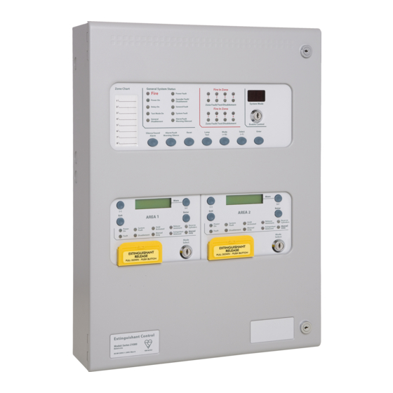
4. Control panel fascias This drawing shows the fascias of the models available in the Sigma XT+ range. K21021M3 K21041M3 K21042M3 K21081M3 K21082M3 K21083M4 K21084M4 The fascias are divided into sections for the detection panel and extinguishant modules. A standard EN54-2 control and indicating equipment section with up to eight zones is located in the top aperture of the panel fascia and EN12094-1 extinguishant modules are fitted in the lower apertures. -
Page 13: Removing The Fire Detection Equipment Chassis
4.1 Removing the fire detection equipment chassis Open the control panel lid using the two 801 lock keys. Before the chassis can be removed it will be necessary to disconnect the power connector terminal block on the left hand side of the PCB. This is fitted on pins and can be pulled towards you to remove it. Do not remove the wires from the terminals. -
Page 14: Connecting To The Circuit Boards
5. Connecting to the circuit boards All connections for field wiring are to rows of terminals along the top and bottom of the circuit boards. Shielded fire alarm cable such as FP200 and metal cable glands must be used for all connections to the panel. The shield of the cable must be bonded securely to the enclosure earth via a metal cable gland. - Page 15 Detection panel terminals Man-1112 Sigma XT+_23 Page 15 of 52...
- Page 16 Extinguishing module terminals Man-1112 Sigma XT+_23 Page 16 of 52...
-
Page 17: Detection Zone Wiring
6. Detection zone wiring The detection zones provide a nominal 20V DC to power conventional detectors and call points as listed in the compatibility tables 2 and 3. The wiring is monitored for open and short circuit fault conditions by removing the 6K8 0.5W end of line monitoring resistors that are supplied fitted to the control panels’... -
Page 18: Using Intrinsically Safe Barriers
8. Using intrinsically safe barriers SIGMA XT+ control panels support the use of I.S. barriers for connecting to equipment in hazardous areas. Only certified detectors, call points and sounders may be used in hazardous areas and these must be connected to the control panel via a compatible I.S. barrier as listed in table 5. Connection of the I.S. -
Page 19: Connection To Monitored Inputs
9. Connection to monitored inputs Monitored inputs (Mode select, manual release, Hold, Abort, Released pressure switch and Low pressure switch) have the same characteristics as detection zone inputs and require a 6K8 0.5W end of line monitoring resistor and a nominal, 470 ohm 1 W trigger resistor. Example of wiring to a monitored input 10. -
Page 20: Igniting Actuator Wiring
10.2 Igniting actuator wiring A maximum of four igniting actuators can be wired in series. If only one or two actuators are fitted, a 2R2, 2.5 Watt resistor must be wired in series with them to provide the correct monitoring resistance. The end of line diode can be discarded when igniting actuators are used. -
Page 21: Connection To Remote Control Terminals
11. Connection to remote control terminals Some functions of the control panel can be controlled externally from the panel if required. The external equipment operating inputs must be restricted by an access level 2 control as defined in EN54-2 The functions are abbreviated at the terminals block on the detection zone PCB in the top part of the control panel as follows: Remote 0 V supply –... -
Page 22: Connection To Relay Contacts
13. Connection to relay contacts Volt free changeover relay contacts are provided for local control and signalling if required. These contacts are rated for switching signalling circuits only and the maximum ratings listed in table 1 should not be exceeded under any circumstances. -
Page 23: Connection And Configuration Of Status Units And Ancillary Boards
14. Connection and configuration of status units and ancillary boards The control panel should not be powered during the connection of status units or ancillary boards. Status units and ancillary boards require a four-wire connection from the associated extinguishing module, which drops into each unit and connects to the corresponding data and power, in and out terminals. -
Page 24: Adding New Status Units/Ancillary Boards
14.1 Adding new status units/ancillary boards When the system is powered up, it will search for connected status units and/or ancillary boards connected to extinguishant modules. If status units or ancillary boards are fitted and detected by the control panel, the LCD will display: ►... - Page 25 The LCD will then display: STATUS UNIT X X = the address of the remaining status units found ENTER TO ACCEPT output unit X X = the address of the remaining ancillary boards unit found ENTER TO ACCEPT When the ENTER button is pressed on the module to which the status units or ancillary boards are connected, the selected status unit or ancillary board will be added to the system and the next unit to be added will be displayed.
- Page 26 SIGMA XT+ EXTINGUISHANT MODULE Status Status serial serial power D1036S ISSUE 04 S/NO. + - + - DISAB HOLD EXTR LED1 F IR E F IR E F IR E MODE RS485 RS485 R23 R26 OU T LED2 T R6 T R5 LED3 T R2...
-
Page 27: Configuring The Panel
15. Configuring the panel 15.1 Detection part Sigma XT+ control panels consist of 2 parts. The detection part has 2, 4 or 8 detection zones and has a number of configuration options which can be set at the time of commissioning to suit the requirements of the installation. These options are normally set once and will rarely need to change. - Page 28 CODE FUNCTION COMMENTS SOUNDER DELAY TIME = 30 SECONDS Sets time delay before sounders operate SOUNDER DELAY TIME = 1 MINUTE combination with configuration codes 31 to 48 and access level 2 function AD. SOUNDER DELAY TIME = 2 MINUTES SOUNDER DELAY TIME = 3 MINUTES SOUNDER DELAY TIME = 4 MINUTES SOUNDER DELAY TIME = 5 MINUTES...
-
Page 29: Extinguishing Modules
CODE FUNCTION COMMENTS ZONE 1 NON-LATCHING Renders the zone self-resetting so that it can be used to receive signals from ZONE 2 NON-LATCHING other systems and will reset when the ZONE 3 NON-LATCHING input is removed. ZONE 4 NON-LATCHING Note: It can take up to 20 seconds for zone to reset ZONE 5 NON-LATCHING itself when sounders are operating ZONE 6 NON-LATCHING... -
Page 30: Configuring The Activation Mode
15.2.3 Configuring the activation mode It is possible to configure the extinguishing modules to be activated by coincidence (any 2 zones in a range of zones) or a single zone in a range of zones. The activation mode is factory set to coincidence. To change this, switch on the enable controls keyswitch and slide the write enable switch on the module to be configured gently to the left. -
Page 31: Reset Inhibit Time
15.2.6 Reset inhibit time It is a requirement of the extinguishing control panel standard EN12094-1 to inhibit reset of the system after it has been activated until there is a signal representing the end of the discharge (a released input) or for an adjustable time period of up to 30 minutes. -
Page 32: Second Stage Alarm Pulsing/Continuous (Alarm Devices As Required By En12094-1)
EXTING. RELEASE TIME = 60 sec. ? To change the time, press the UP or DOWN buttons until the required time is displayed To save the settings, slide the write enable switch gently to the right. The extinguishing release time will now be set to the chosen value. 15.2.10 Second stage alarm pulsing/continuous (alarm devices as required by EN12094-1) The second stage alarm output can be configured to be steady or pulsing at about 1 second on, 1 second off to suit the desired application. -
Page 33: R0V Not Removed On Reset
RELEASE TIMER ENABLED Press the ENTER button and the display will show: RELEASE TIMER To disable the release timer, press the ENTER button. DISABLED To save the settings, slide the write enable switch gently to the right. With the release timer disabled, the extinguishant outputs will remain operated until the system is reset. 15.2.14 R0V not removed on reset It is possible to configure the AUX24V output on the Sigma XT+ module to be removed for a few seconds when the system is reset. -
Page 34: Invert Low Pressure Switch Input
15.2.17 Invert low pressure switch input To enable low pressure switches to be used which have normally closed rather than normally open contacts, it is possible to invert the low pressure switch input. The factory default setting is for the low pressure switch input to use a normally open contact. To invert the low pressure switch input, switch on the enable controls keyswitch and slide the write enable switch on the module to be configured gently to the left. -
Page 35: Panel Operation - Access Levels 1 And 2
exting. o/p 1 level = 206 Press the ENTER button and the display will show: exting. o/p 1 The XXX here will be the actual monitoring level read by the module. level = xxx To save this setting press the ENTER button. To save the settings, slide the write enable switch gently to the right. -
Page 36: Activate Delays
The 7 segment display will show (test zone 1) Press the Mode button until the display shows Press the Enter button. The display will now show the yellow disablement and sounder fault LEDs will be lit. To enable the sounder outputs, press the Mode button while at Access level 2 (Enable keyswitch operated) and scroll with the mode button until is displayed. -
Page 37: Disable Stage 2 Output
16.3.4 Disable Stage 2 output To disable the 2 Stage relay output, press the UP button on the module while at access level 2 until the display shows: DISABLE stage 2 output ? Press the Enter button to select this function. The display will show: ENABLE STAGE 2 OUTPUT ? The yellow disabled LED on the module that has been disabled... -
Page 38: Single Zone Fire Condition
16.4 Single zone Fire condition Upon receipt of a fire condition by activation of a detector or call point, the Common Fire indicator on the detection section will light, the fire buzzer will sound and the zonal Fire indicator(s) will flash at around 2Hz. The fire and local fire relays will also operate and signal any systems to which they are connected. -
Page 39: System Fault - Extinguishant Modules
16.12 System fault – Extinguishant modules The System Fault and general fault LEDs will light if the configuration memory has not been set or has become corrupted. 16.13 General fault – Detection section The General fault LED will be illuminate under any fault condition. This LED will also light if the write enable switch has been left in the access level 3 position and the Enable Controls keyswitch is turned off. -
Page 40: Internal Controls
17. Internal Controls 17.1 Detection part 17.1.1 Watchdog reset If for any reason the microprocessor in the detection part of the control panel fails to carry out its operation correctly it will attempt to restart. This process is called a “watchdog” and the control panel must record and indicate these events. -
Page 41: Address Switch
17.2.5 Address switch Extinguishant modules are connected to the serial bus of the Sigma CP detection part of the control panel and each module must be allocated an address between 1 and 7 using the binary coded DIP switch. The switch setting are shown in this table ADDRESS SWITCH POSITIONS Internal controls on extinguishant modules... -
Page 42: Comms Fault
18.1.6 Comms fault Indicates that communication has been lost with an Extinguishant module, Repeater panel or Ancillary board. Check for comms fault at all Extinguishant modules, Repeaters and Ancillary boards to identify the source of the problem. 18.1.7 Earth fault Indicates that part of the system wiring is connected to earth. -
Page 43: Power Supply
19. Power supply The control panel requires a 230V (+10%/-15%), 50/60Hz, AC mains power supply which connects to the fused terminal block labelled “230V”. Panels with a 3A power supply have a 20mm, F1.6A L250V mains fuse. Panels with a 4A power supply have a 20mm T2A L250V mains fuse. These fuses should only be replaced with fuses of the same or similar types. - Page 44 K21082M3 8 zone two area Current in milliamps Detection section max alarm load Extinguishing module 1 max alarm load Extinguishing module 2 max alarm load Detection section total sounder load (S1&S2) Detection section Aux 24V supply Extinguishant module 1 total sounder load Extinguishant module 2 total sounder load Extinguishant module 1 extinguishant output load Extinguishant module 2 extinguishant output load...
-
Page 45: Maintenance
TEMPERATURE SENSOR WIRE K21083M4 and K21084M4 models have a temperature compensation sensor held in place on the power supply chassis with adhesive tape. The tip of the sensor must be fitted to one of the batteries with the tape supplied for correct temperature compensation. TEMPERATURE SENSOR TAPE... -
Page 46: Ce Mark
23. CE Mark All control panels have a label affixed to the inside of the lid as shown below. This label should not be removed under any circumstances. Man-1112 Sigma XT+_23 Page 46 of 52... -
Page 47: Commissioning Instructions
24. Commissioning instructions 24.1 Before applying power to the panel, any solenoids or igniting actuators must be physically isolated from the system by disconnecting both wires to it. This will prevent any accidental release of extinguishant. 24.2 When power is applied, if all connections are correct, only the green Power On indicators should be lit. If any fault indicators are lit the wiring to the appropriate input or output should be checked an all faults cleared before proceeding. - Page 48 COINCIDENCE ZONE 1 COINCIDENCE ZONE 2 COINCIDENCE ZONE 3 COINCIDENCE ZONE 4 COINCIDENCE ZONE 5 COINCIDENCE ZONE 6 COINCIDENCE ZONE 7 COINCIDENCE ZONE 8 CONFIGURE Z1 FOR I.S BARRIER CONFIGURE Z2 FOR I.S BARRIER CONFIGURE Z3 FOR I.S BARRIER CONFIGURE Z4 FOR I.S BARRIER CONFIGURE Z5 FOR I.S BARRIER CONFIGURE Z6 FOR I.S BARRIER CONFIGURE Z7 FOR I.S BARRIER...
- Page 49 Extinguishant module 1 CONFIGURATION OPTION WRITE SETTING Extinguishant output mode = ACTIVATION MODE = User O/p Mode = FIRST ACTIV. ZONE = LAST ACTV. ZONE = RESET INHIBIT TIME = PRE-REL. DELAY TIME = EXTING. RELEASE TIME = PULSED ACTIV. ALARMS ? STEADY ACTIV.
- Page 50 Extinguishant module 3 CONFIGURATION OPTION WRITE SETTING Extinguishant output mode = ACTIVATION MODE = User O/p Mode = FIRST ACTIV. ZONE = LAST ACTV. ZONE = RESET INHIBIT TIME = PRE-REL. DELAY TIME = EXTING. RELEASE TIME = PULSED ACTIV. ALARMS ? STEADY ACTIV.
- Page 51 Man-1112 Sigma XT+_23 Page 51 of 52...
- Page 52 *Man-1112* Man-1112 Sigma XT+_23 Page 52 of 52...
Need help?
Do you have a question about the Sigma XT Plus and is the answer not in the manual?
Questions and answers