
Subscribe to Our Youtube Channel
Related Manuals for Kentec Electronics Sigma XT Plus


Summary of Contents for Kentec Electronics Sigma XT Plus
- Page 1 Sigma XT+ Extinguishant Coincidence Unit Operation and Maintenance Manual Man-1111 Issue 18 May 2016...
-
Page 2: Table Of Contents
1. INTRODUCTION ................4 2. SAFETY .................... 4 2.1. Static precautions ..........................5 3. MOUNTING ..................5 4. TECHNICAL SPECIFICATION ............... 6 5. FRONT PANEL LAYOUT ............... 8 6. REMOVING THE EQUIPMENT CHASSIS ..........8 ... - Page 3 15.2.8 Select Reserve Solenoid Output (Configuration Option) ........28 15.3 Single input activation ........................28 15.4 Double input activation ......................... 28 15.5 Reset ............................. 28 15.6 Sounder fault ..........................28 15.7 Power fault ........................... 29 ...
-
Page 4: Introduction
1. Introduction The SIGMA XT+ Extinguishant Coincidence Unit is designed in accordance with European standard EN12094-1 Fixed firefighting systems - Components for gas extinguishing systems - Part 1: Requirements and test methods for electrical automatic control and delay devices. The Sigma XT+ ECU is a self contained extinguishant release control unit that can receive activation signals at supervised inputs via volt free contacts from other fire detection control panels or from addressable output modules. -
Page 5: Static Precautions
Operation outside of these limits may render the equipment unsafe. 2.1. Static precautions Installation of the panel should be carried out by qualified personnel only. The electronic components within the panel are vulnerable to physical damage and damage by electrostatic discharges. It is advisable to wear a wrist strap designed to prevent the build-up of static charges within the body, before handling any electronic circuit boards. -
Page 6: Technical Specification
4. Technical specification Table 1 - Electrical specifications ITEM ELECTRICAL RATING COMMENT COMMUNICATION PARAMETERS Mains supply 230V AC, 50Hz +10% - 15% (100 Watts maximum) Standard European mains connection Mains supply fuse F3A 250V TD 20mm Replace only with similar type Power supply rating 5A when battery charging is not required S406 power supply... - Page 7 Table 2 - Compatible sounders Model Type Manufacturer BANSHEE ELECTRONIC VIMPEX WAFER ELECTRONIC VIMPEX FIRECRYER RANGE ELECTRONIC VOICE VIMPEX KOBELL MOTORISED VIMPEX ASKARI ELECTRONIC FULLEON ROSHNI ELECTRONIC FULLEON SQUASHNI ELECTRONIC FULLEON SYMPHONI ELECTRONIC FULLEON ELECTRONIC BELL ELECTRONIC FULLEON CFB BELLS MOTORISED FULLEON B6 AND B8 BELLS...
-
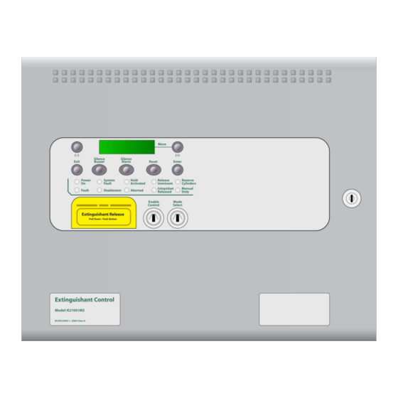
Page 8: Front Panel Layout
5. Front panel layout 6. Removing the equipment chassis Open the control panel lid using the 801 lock key. Before the chassis can be removed it will be necessary to disconnect the power cables from connector terminal block on the left hand side of the PCB. The chassis is held in place by two screws. -
Page 9: System Diagrams
7. System diagrams 2 WIRE RS 485 SERIAL 2 WIRE RS 485 SERIAL 2 WIRE RS 485 SERIAL 2 WIRE RS 485 SERIAL SIGMA CP FIRE PANEL UP TO 4 ECU CONNECTED TO SIGMA CP CONVENTIONAL FIRE PANEL RS 485 SERIAL BUS ADDRESSABLE LOOP ADDRESSABLE ADDRESSABLE... -
Page 10: Connecting To The Circuit Board
8. Connecting to the circuit board All connections for field wiring are to rows of terminals along the top and bottom of the circuit board. Shielded fire alarm cable such as FP200 and metal cable glands must be used for all connections to the panel. The shield of the cable must be bonded securely to the enclosure earth via a metal cable gland. - Page 11 Terminal layout Man-1111_SigmaXT+_Coincidence_Unit_18 Page 11 of 36...
-
Page 12: Sounder Circuit Wiring
8.1. Sounder circuit wiring All sounders must be of the polarised type. If non-polarised sounders are used the control panel will permanently show a fault condition. See table 2 for a list of compatible sounder types. Sounder circuits are monitored for open and short circuit faults by placing a 10K 0.25W end of line monitoring resistor across the last device on the circuit. -
Page 13: Connection To Extinguishant Output
8.2. Connection to extinguishant output The extinguishant output is capable of supplying up to 1 Amp for the maximum duration to a solenoid or 3 Amps for 20 milliseconds to an igniting actuator or Metron. The wiring for solenoids and igniting actuators is different as shown below. Igniting actuators of different types or from different manufacturers should not be mixed on the same circuit. -
Page 14: Connecting To Activation Inputs
8.3 Connecting to activation inputs The ECU has two monitored activation inputs which can be used for activating the system. Each input must have a 6K8 0.5W end of line resistor fitted (supplied in terminals) and be triggered by a 470R 1W resistor. -
Page 15: Connecting To Sigma Cp Fire Panel Serial Bus
8.4 Connecting to Sigma CP fire panel serial bus The ECU may be activated by selected zones from the serial bus of a Sigma CP conventional fire panel if required. The zones that will activate the ECU are selected as described in section 14.3. The terminals marked CIE SERIAL on the lower terminal block of the ECU should be connected to the terminals marked RS485 on the Sigma CP fire panel. -
Page 16: Setting Up Extinguishant Monitoring Circuit
9. Setting up extinguishant monitoring circuit The extinguishing output circuit is factory set to monitor the end of line diode that is fitted to the terminals and will normally show a value of around 270. If the parameters of the extinguishant output change e.g. by connecting a solenoid in parallel with the monitoring diode or removing the diode and fitting igniting actuators, then the extinguishing output monitoring level will need to be “learnt”. -
Page 17: Connection To Relay Contacts
11. Connection to relay contacts Volt free changeover relay contacts are provided for local control and signalling if required. These contacts are rated for switching signalling circuits only and the maximum ratings listed in table 1 should not be exceeded under any circumstances. -
Page 18: Connection And Configuration Of Status Units And Ancillary Boards
12. Connection and configuration of status units and ancillary boards The control panel should not be powered during the connection of status units or ancillary boards. Status units and ancillary boards require a four-wire connection from the panel, which drops into each unit and connects to the corresponding data and power, in and out terminals. -
Page 19: Removing Status Units Or Ancillary Boards
When the ENTER button is pressed, the selected status unit or ancillary board will be added to the system and the next unit to be added will be displayed. Press the ENTER button on the extinguishing module until all of the units have been accepted then gently slide the WRITE ENABLE switch on the module to the right. -
Page 20: Wiring To Status Units And Ancillary Board
13. Wiring to status units and ancillary board The ECU has terminals for data and power connections to Sigma Si status indicator units and/or Sigma XT ancillary boards. These terminals are labelled STATUS SERIAL and STATUS POWER. It is important to wire these terminals with the correct polarity ensuring that + is wired to + and –... -
Page 21: Configuration
14. Configuration 14.1 Language selection The module is capable of displaying two languages if factory programmed to do so. The first access level 3 option is to select the local language or the default language (English) 14.2 Extinguishant output mode The Sigma XT+ module has two extinguishing outputs. -
Page 22: Reset Inhibit Time
Note: The number of the first activation zone must be lower than the last activation zone. To do this, switch on the enable controls keyswitch and slide the write enable switch on the module to be configured gently to the left. Press the ENTER button on the extinguishing module and then the up button until the display will show: FIRST ACTIV. -
Page 23: Extinguishant Release Time
14.8 Output 2 delay If the configured extinguishing output mode is Common (rather than MAIN/RESERVE), it is possible to set extinguishing output 2 to have a further delay of up to 10 minutes in steps of 1 minute. Extinguishing output 2 delay timer will be started when extinguishing output 1 is asserted. This could be used to provide an additional discharge of extinguishing agent to maintain concentration for a longer period of time. -
Page 24: Delay On Manual Release
EXTING. REL To save the settings, slide the write enable switch gently to the right. The released indication will now be lit when the extinguishant outputs operate. 14.12 Delay on manual release The manual release function (panel mounted and remote) can be configured to have a pre-release time delay (as per the set pre-release time) or to have no pre-release delay allowing immediate operation of the extinguishant outputs when a manual release is operated. -
Page 25: Disable Fault Output
switch gently to the left. Press the ENTER button then press the DOWN button until the display shows: EARTH FAULT ENABLED Press the ENTER button and the display will show: EARTH FAULT DISABLED To select this option, press the enter button. To save the settings, slide the write enable switch gently to the right. -
Page 26: Panel Operation - Access Levels 1 And 2
exting. o/p 2 The XXX here will be the actual monitoring level read by the module. level = xxx To save this setting press the ENTER button. To set the monitoring level for extinguishant output 1, press the DOWN button. The display will show: exting. -
Page 27: Disable Stage 1 Output
Turn the Enable keyswitch off to leave the disablement active. To re-enable the manual release facility repeat the procedure above. 15.2.3 Disable Stage 1 output To disable the 1 Stage relay output, press the UP button on the module while at access level 2 until the display shows: DISABLE stage 1 output ? -
Page 28: Select Reserve Solenoid Output (Configuration Option)
TURN OFF EXTraCT OUTPUT ? The yellow disabled LED on the module that has been disabled will be lit. Turn the Enable keyswitch off to leave the Extract output active. To turn off the Extract output, repeat the procedure above. Note: the extract output does not turn off when the module is reset. -
Page 29: Power Fault
stage 1 alarms fault stage 2 alarms fault 15.7 Power fault Failure of the mains power or disconnection of the standby battery will cause the Fault LED to light and the display will show: POWER SUPPLY FAULT 15.8 System fault The System Fault and general fault LEDs will light if the configuration memory has not been set or has become corrupted 15.9 Lamp test... -
Page 30: Watchdog Reset
16.1 Watchdog reset If the microprocessor on an ECU fails to carry out its operation correctly it will attempt to restart. The ECU will show Fault and System Fault LEDs on the front panel, the buzzer will sound and the display will show CPU fault This fault can only be cleared by pressing the Watchdog Reset button.. -
Page 31: Internal Indications
17. Internal indications 17.1 Watchdog Indicates that the processor has failed to correctly execute code and has been re-started by the watchdog circuit. The watchdog reset switch must be pressed to clear the Watchdog fault condition. Press the Watchdog reset button. If system does not return to normal then the module is probably damaged and needs the circuit board replacing. -
Page 32: Maintenance
19. Maintenance Sigma XT+ ECUs do not require any specific maintenance but should the control panel become dirty it can be wiped over with a barely damp cloth. Detergents or solvents should not be used to clean the panel and care must be taken that water does not enter the enclosure. -
Page 33: Ce Mark
20. CE Mark All control panels have a label affixed to the inside of the lid as shown below. This label should not be removed under any circumstances. Man-1111_SigmaXT+_Coincidence_Unit_18 Page 33 of 36... -
Page 34: Commissioning Instructions
21. Commissioning instructions 21.1 Before applying power to the panel, any solenoids or igniting actuators must be physically isolated from the system by disconnecting both wires to it. This will prevent any accidental release of extinguishant. 21.2 When power is applied, if all connections are correct, only the green Power On and either the Automatic and Manual or Manual Only indicators should be lit. - Page 35 Man-1111_SigmaXT+_Coincidence_Unit_18 Page 35 of 36...
- Page 36 *Man-1111* Man-1111_SigmaXT+_Coincidence_Unit_18 Page 36 of 36...
Need help?
Do you have a question about the Sigma XT Plus and is the answer not in the manual?
Questions and answers