
Related Manuals for Kentec Electronics Syncro ASM


Summary of Contents for Kentec Electronics Syncro ASM
- Page 1 Syncro ASM Analogue Addressable Marine Fire Control Panel Product Manual Man-1096M Issue 16 February 2017...
-
Page 2: Table Of Contents
1. INTRODUCTION ........................5 2. SAFETY ........................... 6 3. TECHNICAL SPECIFICATION ....................6 4. INSTALLATION ........................7 5. CABLING ..........................8 5.1 C ........................ 8 ABLE ERMINATION 6. CONNECTING TO THE PANEL ....................9 7. FRONT PANEL CONTROLS ..................... 10 8. - Page 3 18.1.2. Panel address ......................22 18.1.3. Protocol ........................22 18.1.4. Number of loops ....................... 22 18.1.5. Default ringing mode ....................23 18.1.5.1 – Marine Mode ....................... 23 18.1.6. Access level code changes ..................23 18.1.7. CHQ-BS Loop Sounders ..................... 23 18.1.8.
- Page 4 22.1. R ......................32 ECOMMENDED CABLES 22.2. S ......................... 32 OUNDER 22.3. C ....................... 32 URRENT CONSUMPTION 22.4. P – ........................ 32 OWER SUPPLY 22.5. F ........................32 IELD DEVICES 22.6 F 13) ............32 LARM AULT ELAY RATINGS SEE ALSO ECTION 22.7 Z ..........................
-
Page 5: Introduction
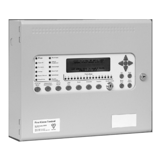
1. Introduction The Syncro ASM is an analogue addressable fire detection and alarm control panel with 16 zonal LED indicators and is available in models with either 1 or 2 detection loops. It can support up to 126 devices for Apollo protocol, up to 127 devices for Hochiki ESP protocol per loop driver. -
Page 6: Safety
2. Safety Suppliers of articles for use at work are required under section 6 of the Health and Safety at Work act 1974 to ensure as reasonably as is practical that the article will be safe and without risk to health when properly used. An article is not regarded as properly used if it is used ‘without regard to any relevant information or advice’... -
Page 7: Installation
4. Installation Installation of the panel should be carried out by qualified personnel only. The electronic components within the panel are vulnerable to physical damage and damage by electrostatic discharges. It is advisable to wear a wrist strap designed to prevent the build-up of static charges within the body, before handling any electronic circuit boards. -
Page 8: Cabling
5. Cabling It is advisable to fit cable glands and cables before re-fitting the outer cover and plate/circuit board assembly. Cables should be brought into the cabinet using the knockouts provided and where necessary, using couplers to maximise the space within the enclosure. -
Page 9: Connecting To The Panel
6. Connecting to the panel All connections to the panel are via 5mm pitch, 2.5mm capacity, spring leaf terminal blocks. Care should be taken to use the correct sized terminal screwdriver and not to over tighten the terminals. If stranded cables are used then care should be taken to ensure that all strands are contained in the terminal and that there are not any loose strands which may cause short circuits to other terminals or cables. -
Page 10: Front Panel Controls
7. Front panel controls The front panel contains controls for operating and programming the panel. The lamp test and silence buzzer buttons can be operated at any time. (Access level 1) The More Fires and More Events buttons can be operated at any time when there are more events than can be displayed on the screen. -
Page 11: Powering The Panel
“Enable” position is with the switch actuator set to the left in the direction of the arrow under the switch. When left in the “Enable” position, a notification message will be given on the Syncro ASM display. This warning message will disappear 1 minute after the switch has been turned off or can be cancelled immediately by operating the front panel Reset button. -
Page 12: Configuring The Panel (Autolearn)
8.2 Configuring the Panel (Autolearn) When supplied, the panel will contain no configuration and when power is first applied the display will show: ***WARNING*** WRITE ENABLE SWITCH IS OFF THE SYSTEM IS HALTED SET WRITE ENABLE AND RESET THE SYSTEM CAREFULLY slide the write enable slide switch (located behind the aperture in the bottom right corner of the plate) to the left position using a small screwdriver, or similar tool. -
Page 13: Configuring The Panel (From Pc)
It is quite common for mistakes to occur when addressing large numbers of devices and it is possible that some devices may have been set to the same address. The control panel can detect devices that have been set to the same address and will announce a “Double address” fault if it finds any. -
Page 14: Facilities Menus
Access level 3 enables a much higher level of control and must be restricted to persons trained and authorised to reconfigure the site-specific data and to maintain the Syncro ASM fire panel. Typically, engineers of the fire systems company will be responsible for Access Level 3 functions. -
Page 15: Fitting Additional Detection Circuit (Loop Card)
10.1 Fitting additional detection circuit (loop card) If an additional detection circuit (loop card) is to be fitted to a single loop Syncro ASM, it must be of the same protocol (Hochiki ESP, Apollo or Argus Vega) as the existing detection circuit. -
Page 16: Loop Sounders & Beacons
Apollo Ancillary base sounders are controlled by the remote indicator output of their host detector. As these sounders are not addressable devices, the Syncro ASM panel will not be able to identify the device during the auto learn sequence. Therefore it is necessary to configure the Syncro ASM panel to advise it that certain detectors have Ancillary Loop sounders installed. -
Page 17: Panel Sounder Circuits
PRE-ALARM FAULT As can be seen from the above, a loop sounder which is sounding a TECH ALARM will change its tone in the event of EVACUATE, FIRE or ALERT events if it is programmed to respond to all of these. Loop sounders can be programmed to operate upon any of the event types using the configure settings window as shown below. -
Page 18: Relays
14. Relays Volt free changeover relay contacts rated at 30 Volts DC at 1 Amp are provided for ancillary switching functions in all panels. Under no circumstances should voltage or current outside of this limit be used with these contacts. The default actions of these contacts as supplied from the factory are as described below: - NAME ACTION... -
Page 19: Remote Control Inputs
16. Remote I/O serial bus The Syncro ASM control panel has a serial communications bus to which additional I/O, relay, sounder and conventional detection zone boards may be connected. The serial bus also supports up to 15 of the full function Syncro View repeater panels. -
Page 20: Channel I/Oboard
16.1 16 channel I/O board The 16 channel I/O boards can be individually configured using the Loop Explorer configuration programme and each channel can be an input or an output. When added to a control panel, all channels default to inputs with and their action when activated will be FAULT. Any or all channels may be changed to outputs via the Loop Explorer configuration programme. -
Page 21: Power Supply
There are two sets of terminals which allow two transmission paths to be accommodated as required by EN54-4 section 6.6. A power fault input is also provided to signal faults from a remote power supply on the Syncro ASM panel. -
Page 22: Programming Via A Pc
Some device manufacturers have calculators available to assist with this. 18. Programming via a PC Due to the use of the very latest microprocessor and memory technology, the Syncro ASM fire control panel is an extremely powerful machine. -
Page 23: Default Ringing Mode
18.1.5.1 – Marine Mode This option applies to the Syncro ASM panel only. When selected, the two panel sounder circuits will operate in an “Abandon Ship” mode (7 short pulses followed by a single long pulse) when an Evacuate input is activated. -
Page 24: Display Invert
etc. Note: Special display screening is required to ensure that the correct indicators are mapped to the appropriate zone label. 18.1.14 – Display Invert This option is used to change the LCD status display format. By default, black lettering is shown on a green background. Selecting this option will change the display to green lettering on a black background. -
Page 25: Network Interface
18.2. Inputs To simplify programming and promote an easy understanding of the system, the operation of the Syncro ASM panel has been designed around a very simple principle. This principle is that all inputs are handled in exactly the same way, whether they are from a loop device, a programmable input on the panel, an I/O board or the programmable pushbutton on the front panel. -
Page 26: Fire Action
ZONE (0-500) LOCATION TEXT (Up to 40 characters) DAY SENSITIVITY NIGHT SENSITIVITY INDICATE PRE-ALARM LOOP SOUNDER FITTED AS DETECTOR BASE INPUT DELAY OUTPUT DELAY BYPASS For all other types of input however, there is an input action attribute, which empowers the system with control possibilities way beyond that of a normal fire alarm. -
Page 27: Reset Action
18.2.9. Reset action An input designated as reset will not produce any visible effect at the control panel but will reproduce the action of the reset button on the panel i.e. reset the alarms. LCD RESET MESSAGE 18.2.10. Transparent action A transparent input will have no effect at all on the panel. -
Page 28: Def Ring Mode
Note: Any output on the Syncro ASM system is treated as a sounder if the Silenceable and Evacuate Output attributes are selected. If any of these outputs are faulty or disabled, the sounder fault/disabled indicator will illuminate. These outputs would also be disabled by the ‘Disable all sounders’ menu option. - Page 29 For more complex applications, it is often a requirement to control plant, ventilation or access control systems in the event of fire situations to assist with evacuation or to provide safety escape routes. Because the Syncro ASM system has inherent flexibility, this is simple to achieve by applying cause and effects to inputs and outputs anywhere on the system.
-
Page 30: Networking
Network boards are fitted with isolators, which disconnect faulty sections of cable and allow the network to continue working by using the return path so it is most important that this wiring configuration be adhered to. A more detailed description of networking capabilities can be found in the Syncro ASM Networking Manual. Product Manuals/Man-1096M_SyncroAS Marine 16... -
Page 31: Panel Settings
21.1. Contrast Adjust The viewing angle/contrast of the Syncro ASM front panel display may be adjusted by turning the CONTRAST adjust potentiometer. The contrast adjust potentiometer can be accessed by opening the front cover of the control panel and is labelled CONTRAST. -
Page 32: Panel Specification Summary
22. Panel specification summary 22.1. Recommended cables All field wiring should be installed using fire rated cables such as FP200, MICC or Fire Tuff types. The minimum cross sectional area should be 1mm although in the case of the detection loops this depends upon the length of the cable and the number and type of devices fitted. -
Page 33: Additional Features
When Syncro ASM control panels are connected as a network, it is possible to perform Access 2 Menu commands on remote panels from any panel on the network. This facility is executed by use of an interim “select panel” menu option whenever the Syncro ASM is installed on a networked system. -
Page 34: View Device Details On Other Panels
23.5. Analogue value transfer If a connection to the Syncro ASM panel is made using the “Connect” screen of Loop Explorer Version 3 (or later), it is possible to transfer the analogue levels, zero calibration and fire calibrations points for each detection device to the PC. -
Page 35: Section 7.2.C / 7.4 / 8.2.1.C / 8.6
Appendix A – EN54 Configuration Requirements In order to meet the requirements of EN54, the panel must be configured with the settings stated below. References refer to EN54 Part 2 1997 clause numbers. Section 7 – Fire Alarm Condition Section 7.1.4 Input delay must be set to zero for all manual call points. -
Page 36: Section 10.1.B
Section 10 – Test Condition Section 10.1.b If a test input type is used as the cause in a test mode cause and effect, this input must be configured so that it is only available at Access level 2, by use of a key input or some other access restriction. This input must be configured as non-latching and can only be cleared by a manual operation at access level 2. - Page 37 EC Type Examination Certificate Number: BSI/A.1/3.51/550734 and EC Production Quality Assurance Certificate module D BSI/MED/PC/550735. The product’s technical file is held by Kentec Electronics Ltd DA1 1JQ This declaration of conformity is issued under the sole responsibility of the manufacturer.
- Page 38 *Man-1096M* Product Manuals/Man-1096M_SyncroAS Marine 16 Page 38 of 38...
Need help?
Do you have a question about the Syncro ASM and is the answer not in the manual?
Questions and answers