Table of Contents
Advertisement
Quick Links
Advertisement
Table of Contents

Related Manuals for Kentec Electronics Sigma ZXT SI


Summary of Contents for Kentec Electronics Sigma ZXT SI
- Page 1 Extinguishant Control Sigma ZXT SI Product Manual *Man-1428* Man-1453 Rev.01...
- Page 2 Safety Suppliers of articles for use at work are required under section 6 of the Health and Safety at Work act 1974 to ensure as reasonably as is practical that the article will be safe and without risk to health when properly used. An article is not regarded as properly used if it is used ‘without regard to any relevant information or advice’...
-
Page 3: Table Of Contents
Contents i Section 1 Introduction ........................1 Supporting Documentation ..........................1 Section 2 Overview ........................... 2 Section 3 Installation and Configuration ..................4 Before You Begin ............................4 Installation checklist ............................4 Mounting the Unit ............................5 Addressing Status Units ..........................6 Electrical Connections .............................6 Connecting to the Circuit Board ........................7 Power and Data Connections .........................8 Data Termination .............................8... -
Page 4: Introduction
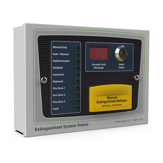
The Sigma ZXT SI Status Units are designed to extend the indications and some controls of Sigma ZXT extinguis- hant control panels to other locations within the fire protection system. They can be introduced to make operation of the system more practical, within areas that have multiple access points (or doors). -
Page 5: Overview
3, 4, 5, 7 & 8 Enclosure lid retaining screw (x2) All items Extinguishant release push-button Manual Release (Extinguishant) 2, 4, 5, 8, 9 (beneath anti-tamper cover) Enclosure knock-outs Cable entry points All items Man-1453 Rev.01 Sigma ZXT SI Product Manual... - Page 6 DIP switch Binary address setting All items Push-buttons Processor and Watchdog Reset All items Status Indicators COM, HOLD, MOD, CPU, FUSE All items Input Terminals E, 24V DC, RS485, MODE, HOLD All items Man-1453 Rev.01 Sigma ZXT SI Product Manual...
-
Page 7: Installation And Configuration
Mount the enclosure to the premises wall using appropriate fixings. Thread external cabling into the enclosure and make connections to unit input terminals (to rear of enclosure lid). Re-fit enclosure lid. Apply power. Configure. Test installation. Man-1453 Rev.01 Sigma ZXT SI Product Manual... -
Page 8: Mounting The Unit
Figure 3-1 Enclosure Back-Box Dimensions (mm). Not to scale. 186.0 143.0 4x 6Ø Figure 3-2 Weather Proof Enclosure Back-Box Dimensions (mm). Not to scale. 257.0 244.0 4x 4.5Ø Man-1453 Rev.01 Sigma ZXT SI Product Manual... -
Page 9: Addressing Status Units
RS485 (+/-),(+/-) RS485 data input from control panel/network. Secondary set of common terminals for connecting other status units. MODE Input terminals for a Mode Select ancillary. HOLD Input terminals for a Hold Off ancillary. Man-1453 Rev.01 Sigma ZXT SI Product Manual... -
Page 10: Connecting To The Circuit Board
Wiring must not go across the front of the circuit board. If cable entries need to be in positions other than at the knock-outs provided, wiring must be fed well away from the surface of the circuit board. Figure 3-5 Wiring Convention INCORRECT CORRECT Man-1453 Rev.01 Sigma ZXT SI Product Manual... -
Page 11: Power And Data Connections
If there is only one status unit fitted then the jumper should be left in place. Man-1453 Rev.01 Sigma ZXT SI Product Manual... -
Page 12: Connection To Hold And Mode Inputs
(0 to 60 seconds). IMPORTANT NOTE: When there is a fault on the HOLD input then the HOLD function is invoked which means that the extinguishant release will not operate until this condition is cleared. Man-1453 Rev.01 Sigma ZXT SI Product Manual... -
Page 13: Modes Select Key-Switch
A switch is also provided to manually re-start the processor PROC RESET. This switch can be used while connected to the system to ensure that unit starts and establishes communication with the Panel in a controlled and expected manner. Figure 3-8 Processor and Watchdog Reset Switches Processor Reset Watchdog Reset Man-1453 Rev.01 Sigma ZXT SI Product Manual... -
Page 14: Status Indicator Led Indications
Three red LED’s which when illuminated indicate a fire on the associated detection zone 1, 2 or 3. Fault An amber LED Indicates an active fault condition on the system, extinguishing control panel will provide specific de- tails on the fault type. Man-1453 Rev.01 Sigma ZXT SI Product Manual... -
Page 15: Controls & Internal Indications
Manual Release has been tampered with. Figure 5-2 Manual Release Push-Button Manual Extinguishant Release Pull Down - Push Button Figure 5-3 Manually Activating Extinguishant Release Process Man-1453 Rev.01 Sigma ZXT SI Product Manual... -
Page 16: Processor And Watchdog Reset Switches
This LED indicates that the electronic fuse has operated. Under this condition, the status unit is not operational. This may be due to incorrect polarity of the power connection or a failure on the unit itself. Man-1453 Rev.01 Sigma ZXT SI Product Manual... -
Page 17: Adding/Removing Status Indicators & Ancillary Boards
3. To install the Status Indicators enter the Engineering Menu (Access Level 3) on the LCD and select the CONNECTED DEVICES menu option. Figure 6-2 Connected Devices *****ENGINEERING MENU***** >CONNECTED DEVICES.. SYSTEM SETTINGS.. USER SETTINGS.. CIE ZONE SETTINGS.. ECD SETTINGS.. PROG I/P SETTINGS.. BACK goto menu Man-1453 Rev.01 Sigma ZXT SI Product Manual... - Page 18 ZXT panel SI Bus which has not yet been regis- UNEXPECTED tered on the panel. Unexpected devices will be indicated as ageneral fault on the ZXT panel. Indicates a device has been removed or is no MISSING longer communicating with the system. Man-1453 Rev.01 Sigma ZXT SI Product Manual...
- Page 19 The status will change to OPERATIONAL in the status line and the graphic symbol for this address will change to □. The status LEDs should display their normal state and any buzzers will stop sounding. Complete this for all unexpected devices until all devices are logged on to the panel. Man-1453 Rev.01 Sigma ZXT SI Product Manual...
-
Page 20: Removing A Status Indicator
Note: Status Indicators can be un-installed from the configuration while being left as part of the physical circuit, how- ever this will cause the Status Unit to flash all LED’s and sound its local buzzer (if fitted) to indicate a ‘comms’ fault. Man-1453 Rev.01 Sigma ZXT SI Product Manual... -
Page 21: Adding An Ancillary Board To A Zxt
PROG I/P SETTINGS.. BACK goto menu 4. In the CONNECTED DEVICES screen, select the REMOTE BUS option to open the REMOTE BUS STATUS screen. Figure 6-9 Remote Bus ****connected devices**** >remote bus.. BACK goto menu Man-1453 Rev.01 Sigma ZXT SI Product Manual... - Page 22 The status will change to OPERATIONAL in the status line and the graphic symbol for this address will change to . Complete this for all unexpected devices until all devices are logged on to the panel. Man-1453 Rev.01 Sigma ZXT SI Product Manual...
-
Page 23: Removing An Ancillary Board
4. To remove the device from the ZXT configuration press the enter button (UNINSTALL) the status line for this address will show none and the graphical status icon will show. 5. The device has now been removed from the system and any associated faults will have cleared. Man-1453 Rev.01 Sigma ZXT SI Product Manual... -
Page 24: Panel Maintenance
Gently clean using a soft dry cloth to remove dust and dirt. If the enclosure is heavily contaminated, moisten the cloth and gently clean W921100W8 using a light detergent. W921110W8 Important! Avoid getting detergent on any status Indicator controls. W921113W8 Man-1453 Rev.01 Sigma ZXT SI Product Manual... -
Page 25: Specifications
Maximum 1200m Maximum number of Status Units Maximum number of Ancillary Boards Product dimensions Product weight Operating temperature range Ingress Protection (IP Rating) IP30 Standard versions Ingress Protection (IP Rating) IP60 Weatherproof versions Man-1453 Rev.01 Sigma ZXT SI Product Manual...
Need help?
Do you have a question about the Sigma ZXT SI and is the answer not in the manual?
Questions and answers