Sign In
Upload
Manuals
Brands
Kentec Electronics Manuals
Control Unit
Sigma XT Plus
Kentec Electronics Sigma XT Plus Manuals
Manuals and User Guides for Kentec Electronics Sigma XT Plus. We have
2
Kentec Electronics Sigma XT Plus manuals available for free PDF download: Operation And Maintenance Manual
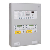
Kentec Electronics Sigma XT Plus Operation And Maintenance Manual (52 pages)
Extinguishant Control Panel
Brand:
Kentec Electronics
| Category:
Control Panel
| Size: 1 MB
Table of Contents
Table of Contents
2
Introduction
5
2 Safety and Mounting
6
Safety
6
Mounting
7
3 Technical Specification
8
4 Control Panel Fascias
12
Removing the Fire Detection Equipment Chassis
13
5 Connecting to the Circuit Boards
14
6 Detection Zone Wiring
17
7 Sounder Circuit Wiring (Alarm Devices as Required by EN12094-1)
17
8 Using Intrinsically Safe Barriers
18
9 Connection to Monitored Inputs
19
10 Connection to Extinguishant Output
19
Solenoid Wiring
19
Igniting Actuator Wiring
20
Setting up Extinguishant Monitoring Circuit
20
11 Connection to Remote Control Terminals
21
12 Aux 24V DC Supply Outputs (Extinguishant Modules Only)
21
13 Connection to Relay Contacts
22
Common Fault Relay (on Detection Part of Control Panel)
22
Fault Relay (on Extinguishing Part of Control Panel)
22
Local Fire Relay (on Detection Part of Control Panel)
22
Fire Relay (on Detection Part of Control Panel)
22
St Stage Alarm Relay (on Extinguishing Modules)
22
2Nd Stage Alarm Relay (on Extinguishing Modules)
22
Released Relay (on Extinguishing Modules)
22
Aborted Relay (on Extinguishing Modules)
22
Extract Relay (on Extinguishing Modules)
22
14 Connection and Configuration of Status Units and Ancillary Boards
23
Adding New Status Units/Ancillary Boards
24
Removing Status Units or Ancillary Boards
24
15 Configuring the Panel
27
Detection Part
27
Extinguishing Modules
29
Language Selection
29
Extinguishant Output Mode
29
Configuring the Activation Mode
30
Configuring the Activation Zones
30
Reset Inhibit Time
31
Pre-Release Delay Time
31
Output 2 Delay
31
Extinguishant Release Time
31
Second Stage Alarm Pulsing/Continuous (Alarm Devices as Required by EN12094-1)
32
Released Indication
32
Delay on Manual Release
32
Release Timer (Infinite Extinguishant Duration)
32
R0V Not Removed on Reset
33
15Disable Earth Fault Monitoring
33
Disable Fault Output
33
Invert Low Pressure Switch Input
34
Invert Released Pressure Switch Input
34
19Extinguishant Output Monitoring Levels
34
16 Panel Operation - Access Levels 1 and 2
35
Normal Condition
35
Detection Section - Access Level 2
35
Test Mode
35
Disable Zones
35
Disable Sounder Outputs
35
Activate Delays
36
Extinguishant Modules - Access Level 2
36
Disable Extinguishant Release Outputs
36
Disable Manual Release
36
Disable Stage 1 Output
36
Disable Stage 2 Output
37
Disable Released Output
37
Disable Extract Output
37
Turn on Extract Output
37
Select Reserve Solenoid Output (Configuration Option)
37
Single Zone Fire Condition
38
Double Zone Fire Condition
38
Silence/Sound Alarms
38
Reset
38
Detection Zone Fault
38
Sounder Fault
38
Power Fault
38
System Fault - Detection Section
38
System Fault - Extinguishant Modules
39
General Fault - Detection Section
39
Lamp Test
39
Hold Condition
39
Released Condition
39
Low Pressure Switch
39
Manual Only Mode
39
17 Internal Controls
40
Detection Part
40
Watchdog Reset
40
Processor Reset
40
Write Enable Switch
40
Extinguishant Modules
40
Terminate Extinguishant
40
Address Switch
41
18 Internal Indications
41
Detection Part
41
Mains Fail
41
Batt Fail
41
CPU Fault
41
Aux 24V Fault
41
Batt Low
41
Comms Fault
42
Earth Fault
42
Sys Fuse Fault
42
S1 Fault
42
S2 Fault
42
Extinguishant Modules
42
Watchdog
42
System Fuse
42
Man. Release
42
19 Power Supply
43
21 Maintenance
45
23 CE Mark
46
24 Commissioning Instructions
47
Advertisement
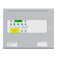
Kentec Electronics Sigma XT Plus Operation And Maintenance Manual (36 pages)
Extinguishant Coincidence Unit
Brand:
Kentec Electronics
| Category:
Control Unit
| Size: 1 MB
Table of Contents
Table of Contents
2
1 Introduction
4
2 Safety
4
Static Precautions
5
3 Mounting
5
4 Technical Specification
6
5 Front Panel Layout
8
6 Removing the Equipment Chassis
8
7 System Diagrams
9
8 Connecting to the Circuit Board
10
Sounder Circuit Wiring
12
Connection to Extinguishant Output
13
Solenoid Wiring
13
Igniting Actuator Wiring
13
Connecting to Activation Inputs
14
Connecting to Sigma CP Fire Panel Serial Bus
15
9 Setting up Extinguishant Monitoring Circuit
16
10 Aux 24V DC Supply Outputs
16
11 Connection to Relay Contacts
17
Fault Relay
17
St Stage Alarm Relay (on Extinguishing Modules)
17
2Nd Stage Alarm Relay (on Extinguishing Modules)
17
Released Relay (on Extinguishing Modules)
17
Aborted Relay (on Extinguishing Modules)
17
Extract Relay (on Extinguishing Modules)
17
12 Connection and Configuration of Status Units and Ancillary Boards
18
Adding New Status Units/Ancillary Boards
18
Removing Status Units or Ancillary Boards
19
13 Wiring to Status Units and Ancillary Board
20
14 Configuration
21
Language Selection
21
Extinguishant Output Mode
21
Configuring the Activation Mode
21
Configuring the Activation Zones (Sigma CP Panel Connection Only)
21
Reset Inhibit Time
22
Pre-Release Delay Time
22
Extinguishant Release Time
23
Second Stage Alarm Pulsing/Continuous
23
Released Indication
23
Delay on Manual Release
24
Release Timer (Infinite Duration)
24
R0V Not Removed on Reset
24
Disable Earth Fault Monitoring
24
Disable Fault Output
25
Invert Low Pressure Switch Input
25
Extinguishant Output Monitoring Levels
25
15 Panel Operation - Access Levels 1 and 2
26
Normal Condition
26
Access Level 2
26
Disable Extinguishant Release Outputs
26
Disable Manual Release
26
Disable Stage 1 Output
27
Disable Stage 2 Output
27
Disable Released Output
27
Disable Extract Output
27
Turn on Extract Output
27
Select Reserve Solenoid Output (Configuration Option)
28
Single Input Activation
28
Double Input Activation
28
Reset
28
Sounder Fault
28
Power Fault
29
System Fault
29
Lamp Test
29
Hold Condition
29
Released Condition
29
Low Pressure Switch
29
Manual Only Mode
29
Manual Release
29
Abort Input
29
16 Internal Controls
29
Watchdog Reset
30
Processor Reset
30
Terminate Extinguishant
30
Write Enable Switch
30
Address Switch
30
17 Internal Indications
31
Watchdog
31
System Fuse
31
Man. Release
31
18 Power Supply
31
19 Maintenance
32
20 Ce Mark
33
21 Commissioning Instructions
34
Advertisement
Related Products
Kentec Electronics S793
Kentec Electronics S792
Kentec Electronics Sigma CP K Series
Kentec Electronics Sigma CP T Series
Kentec Electronics Sigma XT+
Kentec Electronics Sigma A-CP
Kentec Electronics Sigma ZXT
Kentec Electronics Sigma ZXT SI
Kentec Electronics Syncro ASM
Kentec Electronics Solo 2 Lite
Kentec Electronics Categories
Control Panel
Control Unit
Fire Alarms
Measuring Instruments
Controller
More Kentec Electronics Manuals
Login
Sign In
OR
Sign in with Facebook
Sign in with Google
Upload manual
Upload from disk
Upload from URL