Table of Contents
Advertisement
Advertisement
Table of Contents

Subscribe to Our Youtube Channel
Related Manuals for Kentec Electronics Sigma CP K Series


Summary of Contents for Kentec Electronics Sigma CP K Series
-
Page 2: Table Of Contents
Index Page 0 B 1 . Introduction ......................... 3 1 B 2 . Safety and mounting ......................3 2 B 3 . Technical specification ......................4 3 B 4 . Using intrinsically safe barriers ....................8 4 B 5 . Control panel fascia....................... 9 5 B 6 . -
Page 3: Introduction
1 . Introduction The SIGMA CP range consists of a series of conventional fire alarm control panels designed in accordance with European standards EN54-2 and EN54-4 Fire Detection and Fire Alarm systems - Control and Indicating Equipment. The range consists of 2, 4 and 8 zone control panels. All control panels are available in two versions: Sigma K11 range in which detectors and call points are wired on separate circuits to sounders (two sounder circuits are provided). -
Page 4: Technical Specification
Mounting The control panel should be mounted on a dry, flat surface, at eye height to the display and in a level position such that the enclosure is not distorted. Screws or bolts of a minimum of 5mm diameter must be used to mount the enclosure in all three mounting positions. - Page 5 Table 3 - Battery charge voltage versus temperature Temperature Battery charge voltage 29.2 28.56 27.99 27.55 27.13 Table 4 - Compatible detectors Model Type Manufacturer Maximum Number per zone SLR-E OPTICAL Hochiki SLR-E3N OPTICAL Hochiki SIJ-E IONISATION Hochiki DCD-1E HEAT Hochiki DCD-2E HEAT...
- Page 6 Although the current consumption of many detection devices would allow more than 32 to be connected to a zone, this number should be limited to 32 to ensure that a short or open circuit on the wiring does not prevent the indication of a fire alarm from more than 32 fire detectors and/or call points as required by European standard EN54-2.
- Page 7 Table 5 - Compatible detector bases and call points Model Type Manufacturer Comments YBN-R/4 STANDARD Hochiki YBO-R/5 STANDARD WITH REMOTE LED Hochiki YBM-R/6 STANDARD BASE Hochiki YBN-R/4SK DIODE BASE Hochiki Must be used with LCMU* YBO-R/5SK DIODE BASE WITH REMOTE LED Hochiki Must be used with LCMU* YBO-R/6SK...
-
Page 8: Using Intrinsically Safe Barriers
4 . Using intrinsically safe barriers SIGMA CP control panels support the use of I.S. barriers for connecting to equipment in hazardous areas. Only certified detectors, call points and sounders may be used in hazardous areas and these must be connected to the control panel via a compatible I.S. barrier as listed in table 7. Connection of the I.S. -
Page 9: Control Panel Fascia
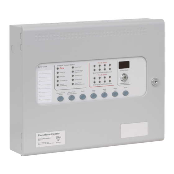
5 . Control panel fascia In addition to the mandatory controls and indications required by the EN54-2 standard, two, seven segment, LED displays and MODE, SELECT and ENTER buttons are provided to allow easy entry and storage of codes to configure the control panel to suit the requirements of the installation. Removing the fascia Before the fascia can be removed it will be necessary to unplug the three way terminal block on the left hand side of the PCB. -
Page 10: Connecting To The Circuit Board
6 . Connecting to the circuit board All connections for field wiring are to a single row of terminals along the top of the circuit board. The connections for the power cables are to a pluggable terminal block which may be pulled off of the board to remove the plate/PCB assembly. -
Page 11: Detection Zone Wiring
8 . Detection zone wiring The detection zones provide a nominal 24V DC to power conventional detectors and call points as listed in the compatibility tables on pages 6 and 7. The wiring is monitored for open and short circuit fault conditions by removing the 6K8 end of line monitoring resistors that are supplied fitted to the control panels’... -
Page 12: Sounder Circuit Wiring
9 . Sounder circuit wiring Whether using standard or T series control panels, all sounders must be of the polarised type. If non- polarised sounders are used the control panel will permanently show a fault condition. See table 6 on page 7 for a list of compatible sounder types. -
Page 13: 0 B 1 1. Aux 24V Dc Supply
1 1. Aux 24V DC supply 1 0 B An auxiliary 24V DC supply is provided to enable local signalling or control of ancillary systems such as door release controllers. The terminals for the Aux 24V supply are labelled Aux 24V and ROV. The ROV terminal is the negative terminal and is the same terminal that should be used to switch the remote control terminals. -
Page 14: 3 B 1 4. Connection To Ancillary Boards
For panels with software version Sigma242.hex or below, the Enable controls keyswitch and Write Enable switch must both be set to off. 1 4. Connection to Ancillary boards 1 3 B Ancillary boards connect via a 2 core cable to the terminals marked RS485 + and – on the Sigma CP main control panel PCB. -
Page 15: 6. Panel Operation
1 6. Panel operation 1 5 B 1 6.1 Normal condition 2 4 B Power On Under normal conditions, control panels will have only the green, LED lit. 1 6.2 Fire condition 2 5 B Common Fire Upon receipt of a fire condition by activation of a detector or call point, the indicator will light Fire and the zonal... -
Page 16: 6 B 1 7. Configuration Options
Note: The flashing “dx” indicator will only appear on panels with software version sigma_CP 214.hex and higher produced after July 2012. 1 6.10.2 Disable sounders 3 5 B To disable sounder outputs, press the mode button to select “db” on the seven segment display. Pressing Disable Sounder Fault enter will disable all sounders and cause the... - Page 17 ZONE 1 I.S. BARRIER ZONE 1 I.S. BARRIER OPTION SET OPTION NOT SET NO DOT FLASHING Figure 9 – Example display showing option set and not set. Table 8 – Configuration codes CODE FUNCTION COMMENTS SOUNDER DELAY TIME = 30 SECONDS Sets the time delay before sounders operate in combination with configuration codes 31 to 48 and access level 2 function AD.
- Page 18 CONFIGURE Z1 FOR I.S BARRIER Detection threshold changed for use with IS barrier CONFIGURE Z2 FOR I.S BARRIER CONFIGURE Z3 FOR I.S BARRIER CONFIGURE Z4 FOR I.S BARRIER CONFIGURE Z5 FOR I.S BARRIER CONFIGURE Z6 FOR I.S BARRIER CONFIGURE Z7 FOR I.S BARRIER CONFIGURE Z8 FOR I.S BARRIER CODE FUNCTION...
-
Page 19: 7 B 1 8. Watchdog Reset Switch
Once the required configuration options have been set, the Write enable switch must be returned to its normal position to the right. The General fault indicator will remain lit if the Write enable switch is not turned off. 1 8. Watchdog reset switch 1 7 B If for any reason the microprocessor in the control panel fails to carry out its operation correctly it will attempt to restart itself. -
Page 20: 5 B 2 0.7 Sys Fuse Fault
2 0.7 Sys fuse fault 4 5 B Indicates that the total power rating of the power supply has been exceeded and that the system fuse has come into operation. Remove and review all loads and re-connect one at a time until over rated circuit trips fuse to identify troublesome circuit. -
Page 21: Power Supply
21. Power supply The control panel requires a 230V (+10%/-15%), 50/60Hz, AC mains power supply which connects to the fused terminal block labelled “230V”. The fused terminal block contains a 20mm, F1.6A L250V fuse which should only be replaced with a similar type. -
Page 22: Maintenance
22. Maintenance Sigma CP control panels do not require any specific maintenance but should the control panel become dirty it can be wiped over with a damp cloth and should then be dried with a dry, lint free cloth. Detergents or solvents should not be used to clean the panel and care must be taken that water does not enter the enclosure. -
Page 23: 3 B 2 4. Record Of Configuration
2 4. Record of Configuration 2 3 B Use the table below to record the configuration codes that have been set on the control panel for future reference. Place a tick in the grey band for any configuration options that are set. It is recommended that a copy of this table is left with the control panel under the supervision of the person responsible for the fire detection system. - Page 24 CODE FUNCTION COMMENTS ZONE 1 SHORT CIRCUIT INDICATES ALARM Changes the trigger threshold of the zone so that the control panel can be ZONE 2 SHORT CIRCUIT INDICATES ALARM used on older systems that had no short ZONE 3 SHORT CIRCUIT INDICATES ALARM circuit monitoring.
Need help?
Do you have a question about the Sigma CP K Series and is the answer not in the manual?
Questions and answers