
Related Manuals for Kentec Electronics Solo 2 Lite


Summary of Contents for Kentec Electronics Solo 2 Lite
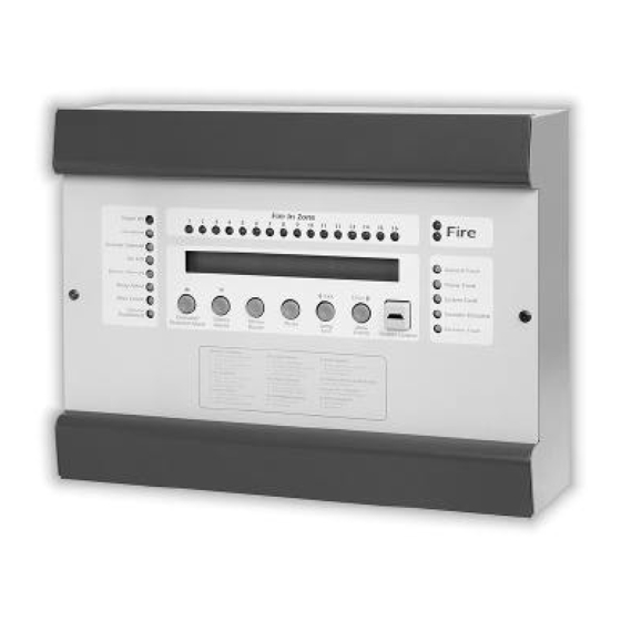
- Page 1 Issue A April 2002 Solo 2 Lite Single Loop Analogue Addressable Fire Control Panel Installation Commissioning & Operating Manual Issue A April 2002...
- Page 2 Issue A April 2002...
- Page 3 Issue A April 2002 Contents ......................5 INTRODUCTION 2. SAFETY .......................... 6 3. INSTALLATION ......................6 4. CABLING........................7 5. POWERING THE PANEL ....................7 5.1 Starting the Panel for the first time ....................7 5.2 Starting a panel that has already been configured ..............
-
Page 4: Table Of Contents
Issue A April 2002 10. USER FACILITIES MENU – (ACCESS LEVEL 2) ............. 16 10.1 Disablements ..........................16 10.1.1 Enable / Disable Zones........................ 16 10.1.2 Enable / Disable Addresses......................16 10.1.3 Disable Panel Outputs ......................... 17 10.1.3.1 Enable / Disable Fire Contact ........................17 10.1.3.2 Enable / Disable Fault Contact ........................17... - Page 5 Issue A April 2002 1. Introduction Solo Lite is an analogue addressable fire detection and alarm control panel capable of covering a maximum of 16 zones with up to 127 individual Hochiki ESP or 126 Apollo S90 / XP95 / Discovery and XPlorer communications protocol devices.
- Page 6 Issue A April 2002 2. Safety Suppliers of articles for use at work are required under section 6 of the Health and Safety at Work act 1974 to ensure as reasonably as is practical that the article will be safe and without risk to health when properly used.
- Page 7 Issue A April 2002 4. Cabling Cables should be brought into the cabinet using the knockouts provided and using couplers to maximise the space within the enclosure. Inlet bushings or cable glands should be used to maintain insulation. The screen or drain wires should be bonded to the earth terminals provided. The maximum size of cable, which can be terminated, is 2.5 mm.
- Page 8 Issue A April 2002 6. Programming the Panel from the P.C. Application If the system has been planned and the devices addressed carefully, commissioning the system using the PC configuration utility should be simple and straightforward. The PC configuration utility has many benefits over manual configuration such as defining cause and effect logic, rapid message allocation, suppliers name entry, day / night mode setting and storage / retrieval of site data and is strongly recommended as the preferred method of data entry.
- Page 9 Issue A April 2002 If the two configurations match, and there is no field wiring or device problems the panel will display the time and date and the suppliers name (if entered on the PC configuration program). The system is now running normally and should be thoroughly tested to verify that all devices location and zone references are correct and output device switching meets the system requirements.
- Page 10 Issue A April 2002 Press the "q (Silence)" button again - the display will change to: CONFIGURATION MENU Transfer configuration to PC Press the "u Enter (More Events)" button to select: PC CONFIGURATION Awaiting link, system not operational On the PC, select "get from panel" option from the toolbar buttons. The PC will display a progress bar indicating each part of the configuration being sent.
- Page 11 Issue A April 2002 7. Configuring the panel without a P.C. Limited configuration changes may be made to the system, by use of the front panel Engineering menu options. These menu options permit the user to allocate zones and a 40-character message to device addresses as well as setting delays to outputs.
- Page 12 Issue A April 2002 The available addresses and local programmable outputs can now be scrolled using the "p (Evacuate)" and "q (Silence)" buttons to select the first address to be allocated. The zone number can be incremented using the "u Enter" button, through the range 1 to 16. When Zone 16 is reached, pressing "u Enter" will set the zone back to Zone 1.
- Page 13 Issue A April 2002 9. Using the Solo Lite Panel Operation of the fire alarm system should be as simple and straightforward as possible. Solo Lite maintains this philosophy by utilising the minimum number of controls and highlighting the most important indications. This ensures that a concise and unambiguous indication of the status of the system is presented to the user at all times.
- Page 14 Issue A April 2002 9.1.2.4 More Events – Menu Access When at Access level 2, press and hold the “More Events” button for three seconds to access the User Facilities Menu. 9.2. Front Panel Indications 9.2.1 Fire Indicators The primary indications on the control panel are those associated with the fire condition. A common fire indicator will illuminate in the event of a fire detector, call point or input device being operated, accompanied by one or more "Fire in Zone"...
- Page 15 Issue A April 2002 9.2.3.7 More Events The "More Events" indicator will be illuminated whenever there are events on the control panel that are not currently displayed in the LCD status window. This would typically be seen in the situation where more than one device is disabled or if there are multiple faults or fires on the system.
-
Page 16: User Facilities Menu - (Access Level 2)
Issue A April 2002 10. User Facilities Menu – (Access Level 2) A number of User Facilities are provided by a menu structure, which can only be accessed at Access Level To access the User Facilities menu, set the panel in to Access Level 2, using the Enable key. Press and hold down the "u Enter (More Events)"... -
Page 17: Disable Panel Outputs
Issue A April 2002 Only fire inputs are suppressed during disablements. The "More Events" button can be used to view all active disablements at access level 1. Addresses can be re-enabled using the same procedure as for disabling. 10.1.3 Disable Panel Outputs This menu option has two sub-menu selections: 10.1.3.1 Enable / Disable Fire Contact To disable the Fire Contact (labelled as Rem Sig inside the panel), press the "u Enter "... -
Page 18: Set The System Clock
Issue A April 2002 When in test mode, activation of a device in the zone under test will cause a normal response at the control panel and sound the sounders for 2 seconds. The control panel will then self-reset, ready for the next device to be tested. -
Page 19: Engineering Facilities Menu - (Access Level 3)
Issue A April 2002 11. Engineering Facilities Menu – (Access Level 3) To enter the Engineering Facilities Menu, select the Access Level 3 option in the User Facilities Menu. Enter the password (factory set at 1000) using the "p (Evacuate)" and "q (Silence)" buttons, then press and hold "u Enter"... -
Page 20: Configure Output Delays
Issue A April 2002 11.3 Configure Output Delays It is possible to configure outputs to be delayed between 30 seconds and 10 minutes from the activation of a smoke detection device. When an output is delayed, the Delay Active LED will be illuminated. The delay will be cancelled by the activation of two devices or a single manual call point. -
Page 21: Clear Event Register
Issue A April 2002 11.4.2 Clear Event Register Once the panel has been commissioned the information can be cleared from the event log by pressing the "u Enter" button. The display will show: CLEAR EVENT REGISTER Event register cleared 11.5 Access Level 2 This option takes the engineer out of the Engineering Facilities Menu, back into the User Facilities Menu at the Disablements menu option. -
Page 22: Loop Sounder Outputs
Issue A April 2002 Sounder circuit fuses are of the self-reset type and require no maintenance or replacement. 12.2. Loop Sounder Outputs The Solo Lite control panel will support loop sounders, although due to current restrictions, the number of sounders should not exceed the quantities given in the graph below; For Hochiki protocol systems, the Solo configuration application will verify the design, by checking the percentage of loop sounder capacity available. -
Page 23: Relays
Issue A April 2002 13. Relays All volt free contacts are intended for switching low power and low voltage signals only. Under no circumstances should voltages or currents above the ratings listed below be exceeded. Note: These functions may not be used to provide any "Options with Requirements" as specified in EN54-2 NAME ACTION... -
Page 24: Int (Intermittent)
Issue A April 2002 14.3 INT (Intermittent) This input allows remote activation of all sounders in the intermittent mode (i.e pulsing on and off). When activated the LCD will display "Remote Alert". The input is not latching therefore all sounder outputs will be turned off when the input is removed. -
Page 25: Battery Charger And Psu
Issue A April 2002 circuit, the control panel immediately supplies power and data from both the "Out" and the "In" terminals effectively powering the circuit from both ends at once. Upon detection of a short or open circuit the display shows: LOOP FAULT 001/001 Loop open or short cct... -
Page 26: System Fuse
Issue A April 2002 17. System Fuse To protect against the high current capacity of the battery, a 5 amp 20mm fuse is fitted which disconnects all circuitry (except the current limited battery charger) in the event of a major fault. (See annex 3). Failure of the system fuse is indicated by a blank display, a continuous tone from the internal buzzer and operation of the fault contact. -
Page 27: Technical Specification
Issue A April 2002 This process will continue until there is no adjustment left at which point the panel will display a maintenance fault condition indicating that the sensor should be replaced or cleaned. This calibration routine incorporates a filtering process that eliminates false compensation due to spurious contamination at the time of calibration. -
Page 28: Appendix A. - Solo 2 Lite Panel Restrictions
Issue A April 2002 Appendix A. – Solo Lite Panel Restrictions The Solo Lite panel has a number of optional and mandatory facilities removed, compared with the Solo Panel. These restrictions are listed in this section. If any of these facilities are required then the full Solo will need to be used. -
Page 29: Appendix B. - En54 Configuration Requirements
Issue A April 2002 Appendix B. – EN54 Configuration Requirements. In order to meet the requirements of EN54, the panel must be configured with the settings stated below. References refer to EN54 Part 2 1997 section numbers. Section 7 – Fire Alarm Condition Section 7.6.1 The internal “Reset”... -
Page 30: Appendix C. - Field Wiring And Pcb Details
Issue A April 2002 Appendix C. – Field wiring and PCB details.
Need help?
Do you have a question about the Solo 2 Lite and is the answer not in the manual?
Questions and answers