
Related Manuals for Kentec Electronics Syncro View Marine


Summary of Contents for Kentec Electronics Syncro View Marine
- Page 1 Syncro View Marine Serial LCD Repeater Panel (MK67000M1, MK67750M1, MK67001M1, MK67751M1, MK67000AM1, MK67001AM1) Operation and Maintenance Manual Man-1092M Issue 03 May 2016...
-
Page 2: Table Of Contents
Index Page 1. Introduction ......................3 2. Safety and mounting ....................3 2.1 Safety ..........................3 2.2 Mounting ......................... 4 3. Technical specification ....................5 4. Syncro View fascia ....................6 5. Connecting to the circuit board .................. 8 ... -
Page 3: Introduction
1. Introduction The Syncro View fire alarm annunciator is designed to provide indication and control of the status of the Syncro ASM analogue addressable fire control panel at a remote or multiple remote locations or provide a more compact and pleasing user interface for the fire alarm system in areas where a large control panel would be obtrusive. -
Page 4: Mounting
2.2 Mounting Surface mounting units should be mounted on a dry, flat surface, at eye height to the display and in a level position such that the enclosure is not distorted. Screws or bolts of a minimum of 4mm diameter must be used to mount the enclosure in all three mounting positions. -
Page 5: Technical Specification
3. Technical specification Table 1 - Electrical specifications Construction 18SWG Mild steel - IP30 rated Cable entry 20mm knockouts 5 in top, 5 in rear and 1 in the side Finish BS 00-A-05 light grey, fine texture. Weight 5Kg maximum Mains supply (Mains powered 230V AC +10% - 15% (20 Watts maximum) models only) -
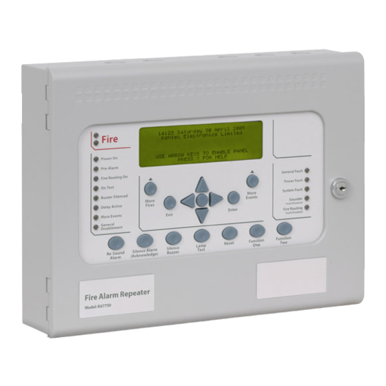
Page 6: Syncro View Fascia
4. Syncro View fascia MK67001 and MK67750 models with enable controls keyswitch MK67000 and MK67751 models without enable controls keyswitch. Page 6 of 13 Product Manuals/Man-1092M_Syncro_View_Marine_03... - Page 7 MK67000AM1 model without enable controls keyswitch. MK67001AM1 model with enable controls keyswitch Page 7 of 13 Product Manuals/Man-1092M_Syncro_View_Marine_03...
-
Page 8: Connecting To The Circuit Board
5. Connecting to the circuit board All connections for field wiring are to a single row of terminals along the bottom of the circuit board. Shielded fire alarm cable such as FP200 and metal cable glands must be used for all connections to the unit. - Page 9 To ensure that the unit is not being subjected to continual, undue interference which may effect its proper operation, a watchdog (W/DOG) LED indicator is latched on and a fault condition signalled to the control panel. If a processor re-start has occurred. this latched fault condition will need to de reset by pressing the W//DOG RESET button on the bottom of the PCB.
-
Page 10: Connecting To The Syncro Asm Panel
NOTE: WIRING TO 24V+ 9. Connecting to the Syncro ASM panel AND 0V TERMINALS NOT REQUITRED ON MAINS POWERED VERSIONS Page 10 of 13 Product Manuals/Man-1092M_Syncro_View_Marine_03... -
Page 11: Connections To Syncro View
10. Connections to Syncro View FIRE ENABLE FIRE POWER ALARM FROUTE FAULT TEST BUZZER FAULT SILENCE FAULT DELAY SOUND FAULT MEVENTS FAULT DISABLE NOTE WIRING TO 24V+ AND 0V TERMINALS NOT REQUIRED ON MAINS POWERED VERSIONS FIT JUMPER COMM2 +24V COMM1 FOR END OF LINE K6017 ISS.03... -
Page 12: Adding A Syncro View To The Syncro Asm Panel
11. Adding a Syncro View to the Syncro ASM panel The Syncro View repeater must be added to the system by configuring the Syncro panel using the Loop Explorer configuration utility. Click on the site name in the left hand window pane to show the option to add panels or repeaters to the system. - Page 13 Right click the Syncro View and select “edit settings” to give the Syncro View a panel name (location) and an address on the serial bus. This address should be different for each Syncro View added and different to any other I/O boards that may exist on the serial bus. Once the configuration file has been loaded into the panel the panel will now expect to see a Syncro View at the address allocated to it and will show a fault condition if the Syncro View is not fitted or is removed.
Need help?
Do you have a question about the Syncro View Marine and is the answer not in the manual?
Questions and answers