
Related Manuals for Kentec Electronics Sigma XT K11031F2


Summary of Contents for Kentec Electronics Sigma XT K11031F2
- Page 1 Sigma XT Extinguishant Control Panel (K11031M2, K11031F2) Operation and Maintenance Manual Man-1088 Issue 26 February 2015...
-
Page 2: Table Of Contents
Page Index 1. Introduction ..........................4 2. Safety and mounting ........................5 2.1 Safety ..........................5 2.2 Mounting ......................... 6 3. Technical specification ......................... 7 4. Control panel fascia ........................10 5. Connecting to the circuit board ....................12 6. - Page 3 15.20.8 Disable manual release ......................25 15.20.9 Disable extract fan ........................25 16. Access level 2 configuration options ..................25 16.1 [ t1 - 3] Test zone ......................25 16.2 [d1 – 3] Disable zone ....................25 ...
-
Page 4: Introduction
1. Introduction The SIGMA XT control panel is designed in accordance with European standards EN54-2 and EN54-4 Fire Detection and Fire Alarm systems - Control and Indicating Equipment and EN12094- 1 Fixed firefighting systems - Components for gas extinguishing systems - Part 1: Requirements and test methods for electrical automatic control and delay devices. -
Page 5: Safety And Mounting
2. Safety and mounting 2.1 Safety Suppliers of articles for use at work are required under section 6 of the Health and Safety at Work act 1974 to ensure as reasonably as is practical that the article will be safe and without risk to health when properly used. -
Page 6: Mounting
2.2 Mounting The control panel should be mounted on a dry, flat surface, at eye height to the display and in a level position such that the enclosure is not distorted. Screws or bolts of a minimum of 5mm diameter must be used to mount the enclosure in all three mounting positions. -
Page 7: Technical Specification
3. Technical specification Table 1 - Electrical specifications ITEM ELECTRICAL RATING COMMENT COMMUNICATION PARAMETERS Mains supply 230V AC, 50Hz +10% - 15% (100 Watts maximum) Standard European mains connection Mains supply fuse 1.6 Amp ( F1.6A L250V) Replace only with similar type Power supply rating 3 Amps total including battery charge 28V +/- 2V Maximum ripple current... - Page 8 Table 2 - Compatible detectors Model Type Manufacturer Maximum Number per zone SLR-E/SLR-E3 OPTICAL Hochiki SIJ-E/ IONISATION Hochiki DCD-1E/DCD-AE3 HEAT Hochiki DCD-2E HEAT Hochiki DCD-1RE/DCD-CE3 HEAT Hochiki DFG-60E HEAT Hochiki DFJ-60E/DFJAE3 HEAT Hochiki DFJ90-E/DFJCE3 HEAT Hochiki SPB-ET BEAM Hochiki SRA-ET BEAM Hochiki 55000-200/210 - SERIES 60...
- Page 9 CT3000 O OPTICAL DETECTOMAT CT3000 T HEAT DETECTOMAT ECO1002 HEAT/PHOTO System Sensor ECO1003 PHOTO System Sensor ECO1005 HEAT System Sensor ECO1005T HEAT System Sensor Although the current consumption of many detection devices would allow more than 32 to be connected to a zone, this number should be limited to 32 to ensure that a short or open circuit on the wiring does not prevent the indication of a fire alarm from more than 32 fire detectors and/or call points as required by European standard EN54-2.
-
Page 10: Control Panel Fascia
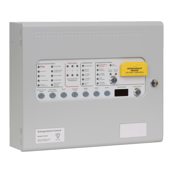
4. Control panel fascia In addition to the mandatory controls and indications required by the EN54-2 and EN12094-1 standards, three, seven segment LED displays and MODE, SELECT and ENTER buttons are provided to allow easy entry and storage of codes to configure the control panel to suit the requirements of the installation. - Page 11 4.1 Removing the fascia Open the control panel lid using the 801 lock key. Before the fascia can be removed it will be necessary to disconnect the power connector terminal block on the left hand side of the PCB. This is fitted on pins and can be pulled towards you to remove it.
-
Page 12: Connecting To The Circuit Board
5. Connecting to the circuit board All connections for field wiring are to a single row of terminals along the top of the circuit board. Shielded fire alarm cable such as FP200 and metal cable glands must be used for all connections to the panel. -
Page 13: Detection Zone Wiring
6. Detection zone wiring The detection zones provide a nominal 20V DC to power conventional detectors and call points as listed in the compatibility tables 2 and 3. The wiring is monitored for open and short circuit fault conditions by removing the 6K8 end of line monitoring resistors that are supplied fitted to the control panels’... -
Page 14: Using Intrinsically Safe Barriers
8. Using intrinsically safe barriers SIGMA XT control panels support the use of I.S. barriers for connecting to equipment in hazardous areas. Only certified detectors, call points and sounders may be used in hazardous areas and these must be connected to the control panel via a compatible I.S. barrier as listed in table Connection of the I.S. -
Page 15: Connection To Monitored Inputs
9. Connection to monitored inputs Monitored inputs (Mode select, manual release, Hold, Released pressure switch and Low pressure switch) have the same characteristics as detection zone inputs and require a 6K8 end of line monitoring resistor and a nominal, 470 ohm trigger resistor. Figure 10. -
Page 16: Igniting Actuator Wiring
10.2 Igniting actuator wiring A maximum of four igniting actuators can be wired in series. If only one or two actuators are fitted, a 2R2, 2.5 Watt resistor must be wired in series with them to provide the correct monitoring resistance. -
Page 17: For 3 Or More Actuators
For 3 or more actuators Rotate the extinguishant adjust control until the Fault lamp lights. By rotating the extinguishant adjust control back and forth the Fault lamp can be toggled on and off, this is usually between ¼ and ½ a turn. Establish these points and leave the extinguishant adjust control set with the Fault lamp just off. -
Page 18: Connection To Remote Control Terminals
11. Connection to remote control terminals Some functions of the control panel can be controlled externally from the panel if required. The external equipment operating inputs must be restricted by an access level 2 control as defined in EN54-2 The functions are abbreviated at the terminals block as follows: a) Remote 0 V supply –... -
Page 19: Connection To Relay Contacts
13. Connection to relay contacts Volt free changeover relay contacts are provided for local control and signalling if required. These contacts are rated for switching signalling circuits only and the maximum ratings listed in table 1 should not be exceeded under any circumstances. Typically, the Aux 24V output of the control panel is switched through these relays and used to control other systems. -
Page 20: Connection And Configuration Of Status Units And Ancillary Boards
14. Connection and configuration of status units and ancillary boards The control panel should not be powered during the connection of status units or ancillary boards. Status units and ancillary boards require a four-wire connection from the panel, which drops into each unit and connects to the corresponding data and power, in and out terminals. -
Page 21: Removing Status Units/Ancillary Boards
14.2 Removing status units/ancillary boards When status units/ancillary boards are to be removed from the system, the system must be powered down first and the status units/ancillary boards removed. The system should then be powered. When the system starts it will be in fault and the units removed will be shown on the display. -
Page 22: Double Zone Fire Condition
15.3 Double zone Fire condition Upon receipt of a second fire condition when the control panel is switched to Automatic and Manual mode, the Hold input is not active, and the Disable Extinguishant Sub-system function has not been invoked, the control equipment will respond as above and as listed below: a) The second stage alarm output will operate. -
Page 23: System Fault
Note: Indication of a mains failure may be delayed by 30 minutes by setting configuration option 15.10 System fault The System Fault LED will light if the configuration memory has not been set or has become corrupt. 15.11 General fault Will illuminate under any fault condition. -
Page 24: Change Mode
Note: The panel will automatically exit test mode if there are no fire activations for 15 minutes. 15.17 Change mode The mode of the system can be toggled between Manual Only and Automatic & Manual by operating the keyswitch in the extinguishant status area of the panel. When the system is in Manual Only mode, the extinguishant cannot be released by the operation of automatic detectors. -
Page 25: Disable Manual Release
15.20.8 Disable manual release The Manual release facility can be disabled by selecting configuration option “dT”. See section 16. 15.20.9 Disable extract fan The extract fan output can be disabled by selecting configuration option “dc”. See section 16. 16. Access level 2 configuration options Turn enable keyswitch to get to access level 2. -
Page 26: Dp] Disable (Pre-Activated) First Stage Relay Contact
16.4 [dP] Disable (pre-activated) first stage relay contact Selecting [dP] shall disable the Preactivated (1 stage) relay output. The 1 Stage Contact disabled and General Disablement indicators shall illuminate whilst the Preactivated relay is disabled. 16.5 [dA] Disable (activated) second stage relay contact Selecting [dA] shall disable the Activated (2 stage) relay output) The 2 Stage Contact disabled... -
Page 27: Access Level 3 Configuration Options
17. Access level 3 configuration options The SIGMA XT control panel has many configuration options which can be set at the time of commissioning to suit the requirements of the installation. These options are normally set once and will rarely need to change. The configuration options are only available at access level 3. To enter access level 3, CAREFULLY slide the Write Enable switch (located behind the aperture in the panel plate) to the right position, using a small screwdriver or similar. - Page 28 Table 5 – Configuration codes NOTE: Setting the options marked with asterisks does not comply with EN54-2 CODE FUNCTION COMMENTS CONFIGURATION UPDATE COUNT Number incremented each time access level 3 config changed. Counter resets to 00 when 99 is reached. SOUNDER DELAY TIME = 30 SECONDS Introduces a time delay before sounders operate.
- Page 29 Z3 DEVICE ALARM MUST BE PRESENT FOR 30 SECONDS PANEL CAN BE RESET IMMEDIATELY DISCHARGE To allow reset of the panel to be prohibited before the OUTPUT HAS OPERATED extinguishant discharge has fully completed. PANEL CAN BE RESET 1 MINUTE TO 29 MINUTES AFTER DISCHARGE OUTPUT HAS OPERATED PANEL CAN BE RESET 30 MINUTES AFTER DISCHARGE OUTPUT HAS OPERATED...
-
Page 30: Internal Controls
18. Internal Controls 18.1 Watchdog reset If for any reason the microprocessor in the control panel fails to carry out its operation correctly it will attempt to restart itself. This process is called a “watchdog” and the control panel must record and indicate these events. -
Page 31: Internal Indications - Troubleshooting
19. Internal indications – troubleshooting To assist in identifying fault conditions which are not detailed on the front of the control panel, a number of internal indicators are visible with the front cover removed as follows: Figure 19. Internal fault LED 19.1 Mains fail Indicates that the 230V AC supply is not present and the system is running on standby batteries. -
Page 32: Earth Fault
19.7 Earth fault Indicates that part of the system wiring is connected to earth. Remove all system wiring and re- connect cables one at a time until the earth fault returns. This will indicate which cable the earth fault is present on. 19.8 Sys fuse fault Indicates that the total power rating of the power supply has been exceeded and that the system fuse has come into operation. -
Page 33: Tell Tale
19.16 Tell tale Indicates that either panel mounted or remote manual release button has been pressed. Can only be reset by pressing processor reset and W/DOG reset or powering down the control panel. Product Manuals/Man-1088_Sigma XT_26 Page 33 of 40... -
Page 34: Power Supply
20. Power supply The control panel requires a 230V (+10%/-15%), 50/60Hz, AC mains power supply which connects to the fused terminal block labelled “230V”. The fused terminal block contains a 20mm, F1.6A L250V fuse which should only be replaced with a similar type. -
Page 35: Maintenance
21. Maintenance SIGMA XT control panels do not require any specific maintenance but should the control panel become dirty it can be wiped over with a barely damp cloth. Detergents or solvents should not be used to clean the panel and care must be taken that water does not enter the enclosure. The control panel contains sealed lead acid batteries to provide standby power in the event of mains failure. - Page 36 C21* DISABLE FIRE BUZZER C22* DISABLE FIRE OUTPUT DISABLE FAULT OUTPUT DISABLE EARTH FAULT MONITORING PULSE R0V OUTPUT REMOVE AUX 24V ON SYSTEM RESET INDICATE EXTING RELEASED WHEN EXTING OUTPUT IS ACTIVE NO ACTIVATION DELAY UPON MANUAL RELEASE EXTINGUISHANT OUTPUT CAN BE RESET DURING IMMINENT PHASE LOCAL FIRE RELAY OPERATES UPON RELEASED SIGNAL...
- Page 37 Figure 22 – System Schematic Product Manuals/Man-1088_Sigma XT_26 Page 37 of 40...
-
Page 39: Ce Mark
23. CE Mark All control panels have a label affixed to the inside of the lid as shown below. This label should not be removed under any circumstances. Product Manuals/Man-1088_Sigma XT_26 Page 39 of 40... -
Page 40: Commissioning Instructions
24. Commissioning instructions 24.1 Before applying power to the panel, the extinguishant device (solenoid or igniting actuator) must be physically isolated from the system by disconnecting both wires to it. This will prevent any accidental release of extinguishant 24.2 When power is applied, if all connections are correct, only the green Power On and either the Automatic and Manual or Manual Only indicators should be lit.
Need help?
Do you have a question about the Sigma XT K11031F2 and is the answer not in the manual?
Questions and answers