Table of Contents
Advertisement
INSTALLATION
MANUAL
FULL DC INVERTER XPOWER VRF OUTDOOR UNIT
Thank you very much for purchasing our air conditioner.
Before using your air conditioner , please read this manual carefully and keep it for future reference.
Caution: The heating function of an indoor unit is available only when it is connected to
a cooling & heating outdoor unit.
Advertisement
Table of Contents

Related Manuals for Carrier Xpower Series


Summary of Contents for Carrier Xpower Series
- Page 1 INSTALLATION MANUAL FULL DC INVERTER XPOWER VRF OUTDOOR UNIT Thank you very much for purchasing our air conditioner. Before using your air conditioner , please read this manual carefully and keep it for future reference. Caution: The heating function of an indoor unit is available only when it is connected to a cooling &...
- Page 3 CONTENTS PAGE Follow these instructions carefully for installation. Improper installation may cause water leaks, electrical shocks, or fires. PRECAUTIONS..................1 CONSTRUCTION CHECKPOINTS..............2 When installing the unit in a small room, keep the refrigerant concentration below the safety limit in case of leaks. ACCESSORIES..................3 Contact the place of purchase for more information.
- Page 4 Do not modify the length of the power supply cord, use an Young children and elderly should not use the unit unsupervised. extension cord, or share an outlet with another electric appliance. Doing so may cause a fire or electric shocks. Young children should be supervised to ensure they do not play with the appliance.
- Page 5 To prevent mis-operating the air conditioner, do not entwine the Creating a vacuum power cable with the connection wires (low-voltage wires) for Use the vacuum pump to create a vacuum with the connective the indoor/outdoor unit. pipe at the gas side and liquid side concurrently. Power on the indoor unit after performing the airtight test and Refrigerant replenishment creating a vacuum.
-
Page 6: Outdoor Unit Installation
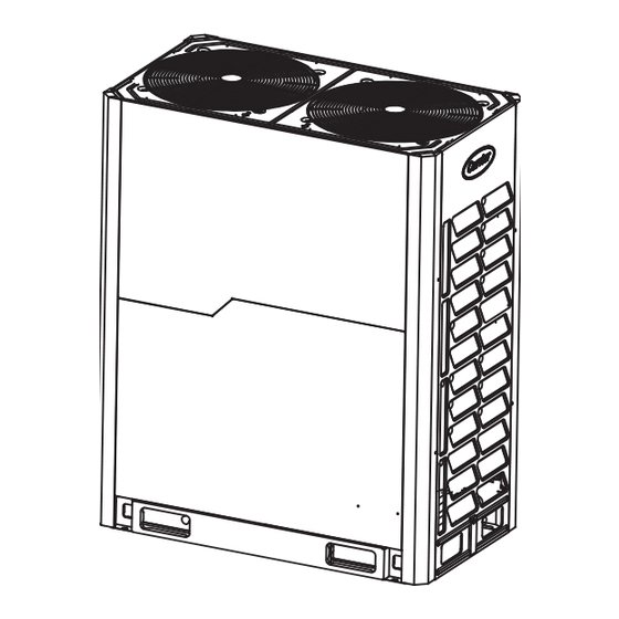
4. OUTDOOR UNIT INSTALLATION 4.1 Outdoor unit combination Table.4-1 (HP) Outdoor unit recommeded Max Qty.of capacity Qty. of indoor units Combination indoor units (HP) ● ● ● ● ● ● ● ● ●● ● ● ● ● ● ● ● ●... - Page 7 4.2 Dimension of outdoor unit 4.3 Selecting the installation position 8~12 HP Unit:mm Ensure that the outdoor unit is installed in a dry, well-ventilated place. Ensure that the noise and exhaust ventilation of the outdoor unit do not affect the neighbors or surrounding ventilation. Ensure that the outdoor unit is installed in a well-ventilated place that is as close as possible to the indoor unit.
- Page 8 If the base is placed on a roof, the detritus layer is not needed, but the concrete surface must be roughened. The standard Gauge point concrete mixture ratio is 1:2:4 (cement:sand:cobblestone), and Detect the pressure / Replenish Φ10 reinforced steel bar must be used. The surface must be refrigerant / create a vacuum Liquid side flattened with cement mortar, and the base borders must be...
- Page 9 More than two rows 4.6 Installation space for outdoor unit Ensure enough space for maintenance. The modules in the >1m same system must be on the same height.(Fig.4-7) When installing the unit, leave space for maintenance, as Front Front shown in Fig.4-8. Install the power supply at the side of the outdoor unit.
- Page 10 4.8 Set the snow-proof function Applies to snowy areas (see the figure below). Defective equipment may cause a malfunction. Lift the bracket and install the snow shed at the air inlet and air outlet. 5~10° Snow shed for air inlet Snow shed for air outlet (Hooks on the upright post;...
- Page 11 4.11 Mount the air deflector Unit: mm Table.4-5 (If the static pressure of outdoor unit is over 20 Pa, the A≥300 unit needs to be customized.) B≥250 8~12HP Installation illustration C≤3000 Example A 731≤D≤770 E=A+731 θ ≤15° θ Example B Support Radius Fig.4-20...
- Page 12 14~22HP Installation illustration Example B 1290 Example A Support Radius 1290 Fig.4-27 Radius Support Radius θ Radius Air outlet louver dimension (optional) θ Fig.4-31 Fig.4-28 12 x ST3.9 self-threading screws 12 x ST3.9 self-threading screws Remove the two iron filters first Remove the two iron filters first Fig.4-29...
- Page 13 Air pressure curve diagram 12HP NOTE (remove the mesh) 12200 ■ Before installing the air deflector, remove the mesh enclosure to avoid blocking the air supply. 12000 ■ Mounting the shutter on the unit limits the air volume, cooling 11800 (heating) capacity, and efficiency depending on the shutter angle.
-
Page 14: Refrigerant Pipe
5. REFRIGERANT PIPE 5.1 Length and drop height permitted of the refrigerant piping Table.5-1 Piping(refer to Fig.5-1) Permitted value 1,000 m Total pipe length (refer to caution 5 of )x2+a+b+c+d+e+f+g+h+i+j+k+l+m (total extended length) conditions 2) Actual length 175m Maximum piping (L) (Pipe diameter requirements. - Page 15 Examples CAUTION Reference Fig.5-1 The reduced length of the branch joint is the 0.5m of the equiva- lent length. The inner units should as equal as possible to be installed in the both sides of the U-shape branch joint. When the outdoor unit is higher and the difference in levels is over 20 m, set an oil return bend every 10 m in the air pipe of the 5.2 Size of joint pipes for indoor unit main pipe.
- Page 16 5.3 Select the refrigerant piping type (140) (71) (12) (12) (22) (140) (28) (140) (140) (140) (140) (71) (28) (140) (56) (56) Fig.5-3 Table.5-5 Size of joint pipes for 410A outdoor unit 5.4 Size of joint pipes for outdoor unit When the equivalent length of all liquid pipes ≥...
- Page 17 Table.5-9 Unit: mm 5.6 Branch pipes for indoor unit When the branch When the branch Based on Tab.5-7 and Tab.5-8, select the multi connection pipes Indoor unit joint’s length ≤10 m joint’s length>10 m for the outdoor unit. Before installation, read the installation capacity manual for Outdoor Unit branch joints.
- Page 18 (140) (71) (12) (12) (22) (140) (28) (140) (140) (140) (140) (71) (28) (140) (56) (56) Fig.5-4 Parallel connect the outdoor units The outdoor unit linked by Pipe g1 is 12HP, which parallel connects with the outdoor unit. Refer to Tab.5-8 the connective pipe g1 diameter is Φ25.4/Φ12.7.
- Page 19 Connect with vacuum pump Run the pump (2 hrs or more) 1. Close the valve in the vacuum meter. When get the vacuum level 2. Cut the connection -0.1MPa, keep the pump between the pressure running for 20-60 mins meter and vacuum pump. 3.
- Page 20 The branch joint must be installed horizontally. The error angle cannot be more than 10° or a fault may occur. U-shaped branch joint Direction view Incorrect Correct 10° 10° Fig.5-14 Horizontal surface Fig.5-11 To stop oil accumulating in the outdoor unit, install the branch joints correctly.
-
Page 21: Electric Wiring
6. ELECTRIC WIRING The display contains the following: 1) Normal display: On standby, the high position displays the address of the outdoor unit, and the low position displays the Qty. 6.1 Sw2 query instructions of indoor units that can communicate with the outdoor units. When Apply the SW2 spot check Table.6-1 running, it will display the rotation frequency of the compressor. - Page 22 CAUTION Set refrigerant piping system, signal wires between indoor-indoor unit, and that between outdoor-outdoor unit into one system. Power must unified supply to all indoor units in the same system. Please do not put the signal wire and power wire in the same wire tube;...
- Page 23 With power facilities 6.5 Electric wiring system and installation Outdoor unit CAUTION Manual Leakage power supply switch protector 380-415V 3N~ 50Hz/60Hz Select the power supply for the indoor units and outdoor units separately. Outdoor unit The power supply should have a specified branch circuit with a leakage protector and manual switch.
- Page 24 Table.6-4 Select the capacity of manual switch and fuse of the branch Total HP <20m <50m box. See the following table. When there are no power facilities, it depends on the outdoor unit it connects to. See table.6-4 below. When there is power, it depends on total horsepower.
- Page 25 6.6 Control system and Installation 6.5.2 Cable clips of main power wire instructions The attached cable clip includes two parts: the base and upper The control line should be shielded wire. Using other wire cover. The base is installed in the electric control box located under will cause signal interference and faulty operations.
-
Page 26: Trial Run
Example for power wire connection Fully turn on the air pipe stop valve, liquid pipe stop valve, oil balance valve, and air balance valve. If the above valves are not turned on fully, the unit will be damaged. Power(380-415V 3N ~ 50Hz/60Hz) L2 L3 N Check whether the power phase sequence of outdoor unit is B C N... - Page 27 Caution on refrigerant leakage Hand over to the customer This air conditioner uses R410A as refrigerant, which is Give the installation manual for the indoor unit and outdoor safe and noncombustible. unit to the user. The room housing the air conditioner should be big enough so that a refrigerant leakage cannot reach critical thickness.
- Page 28 8. CUSTOMER DETAILS Branch Address …………………………………………………………… …………………………………………………………… …………………………………………………………… Telephone …………………………………………………………… Person to be contacted …………………………………………………………… Dealer address …………………………………………………………… …………………………………………………………… …………………………………………………………… Telephone …………………………………………………………… Person to be contacted …………………………………………………………… …………………………………………………………… Signature of the Dealer with Seal. In all correspondence/communication state your name, address, the serial number of your air conditioning unit, date of purchase and dealer’s name (include address), location of unit and description of problem, for prompt and immediate attention Name of Customer...
- Page 29 16127000A06499 V1.0...
Need help?
Do you have a question about the Xpower Series and is the answer not in the manual?
Questions and answers
WHAT IS THE ERRORE 2HD