Table of Contents
Advertisement
Quick Links
Advertisement
Table of Contents

Related Manuals for Carrier X Series


Summary of Contents for Carrier X Series
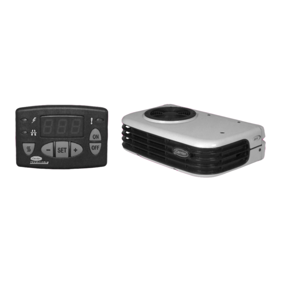
- Page 2 OPERATOR’S MANUAL X Series Truck Direct Drive Truck Refrigeration Units With Cab Command Controller...
- Page 3 NITS OMMAND ONTROLLER This guide has been prepared for the operator of Carrier Transicold X Series direct drive truck refrigeration units using the Cab Command controller. It contains basic instructions for the daily operation of the refrigeration unit as well as safety information, and other information that will help you to deliver the load in the best possible condition.
-
Page 4: Table Of Contents
CONTENTS Page Safety ........Unit Identification . -
Page 5: Safety
AFETY Your Carrier Transicold refrigeration unit has been designed with the safety of the operator in mind. During normal operation, all moving parts are fully enclosed to help prevent injury. During all pre-trip inspections, daily inspections, problem troubleshooting, you may be exposed to moving parts; please stay clear of all moving parts when the unit is in operation. -
Page 6: Unit Identification
If a problem occurs, please refer to the information on this plate, and make a note of the model and serial number before calling for assistance. This information will be needed when you contact a technician or Carrier Transicold Service Engineer so that he or she may properly assist you. NAMEPLATE... - Page 7 A : Evaporator B : Condenser C : Cab Command control D : Compressor E : Vehicle battery 62--10892...
-
Page 8: Symbols Used On Cab Control
YMBOLS USED ON ONTROL Readout Standby operation display (Not Applicable) Road operation display Manual defrost control key Unit start-up key Unit shut-down key Data selection key Selected data decrease key Selected data increase key Unit operation display S Green = in-range (left half) S Red = malfunction (right half) 62--10892... -
Page 9: Unit Operation
PERATION PERATING PRINCIPLE After starting up the refrigeration unit by pressing the ON key on the Cab Command, unit start--up and shut--down are automatic. Road operation, an open--type compressor is driven by the engine of the vehicle. The vehicle battery powers the evaporator and condenser fans. -
Page 10: Starting
TARTING 1. Press ON key. 2. Check if box temperature is displayed. 62--10892... -
Page 11: Temperature Setpoint
EMPERATURE ETPOINT 1. Press SET key to display setpoint. 2. Press + (plus) key to increase setpoint or press -- (minus) key to decrease setpoint. 3. Press SET key when desired setpoint is displayed to lock in new setpoint. 62--10892... -
Page 12: Manual Defrost
ANUAL EFROST 1. Check that box temperature is 40_F or lower. 2. Press Manual Defrost key to initiate manual defrost. 62--10892... -
Page 13: Defrost Interval
EFROST NTERVAL Defrost interval in hours: 0,1, 1.5, 2, 2.5, 3, 4, 5 & 6 AUT: microprocessor optimized automatic defrost according to type of cargo. 1. Press the OFF key. 2. Press Defrost and ON key to display the previously selected defrost interval. 3. -
Page 14: Continuous Airflow
INIMUM ETPOINT, UT-OF- ANGE ONTINUOUS IRFLOW Minimum Setpoint Settings: ---20_F (---28.9_C), ---4_F (---20_C), or 32_F (0_C) Out-of-Range Settings: 1.8, 3.6 or 5.4_F (1, 2 or 3_C) Continuous Airflow Settings: ON or OFF 1. Turn unit on and Press + (plus) key. 2. -
Page 15: Stopping Unit
TOPPING 1. Press the OFF key. 62--10892... -
Page 16: Product Loading
RODUCT OADING BEFORE LOADING: D Pre-cool the body. This will remove much of the heat from the inside of the body, and give the product better protection when it is loaded. D Place the unit in a defrost cycle immediately before loading. This will remove moisture accumulated on the evaporator coil. - Page 17 All products should be kept away from the side-walls of the body, to allow air flow between the body and the load; this prevents heat filtering through the walls from affecting the product. It is important to check the temperature of the product being loaded to ensure that it is at the correct temperature for transport.
-
Page 18: Recommended Transport Temperatures
These are included for reference only and should not be considered preemptive of the set point required by the shipper or receiver. More detailed information can be obtained from your Carrier Transicold dealer. Setpoint Range... -
Page 19: Problems & Alarms
If, however you run into problems the following section may be of assistance. If you do not find the trouble that you have experienced listed, please call your Carrier Transicold dealer for assistance. General Problems Unit won’t power Check battery condition. -
Page 20: Alarm Display
LARM ISPLAY 1. When an alarm is activated, the ! light flashes red. The ! light flashes green when the unit is operating correctly. 2. Press the SET key for 5 seconds to display alarms. 3. Press + (plus) or -- (minus) key to view additional alarms. -
Page 21: Alarm List
LARM ALARM ALARM DESCRIPTION No Malfunction A01/A02 High or Low Pressure Switch Road Compressor Clutch Condenser Fan Motor (high amp draw) Evaporator Fan Motor (high amp draw) Hot Gas Valve (HGS1) (high amp draw) Quench Valve (BPV) (high amps draw) Condenser Pressure Control Valve (HGS2) High Temperature Alarm... -
Page 22: Alarm Reset
LARM ESET 1. Press the OFF key to clear alarm list. Unit can now be restarted if no active alarm condition remains. 62--10892... -
Page 23: Fuses
USES To access the fuses in the control box, remove the upper cowling from unit, then open the control box (fastened by 3 screws). ROAD SUPPLY FUSE Fuse Purpose Fuse Road Supply Fuse 25 A Ignition Fuse (Located in line) Main Road Fuse 40 A Located at vehicle battery... -
Page 24: Unit Maintenance
Refrigerant Charge: R404a Refrigerant Charge Unit Charge 3.1 lbs (1.4 kg) 3.7 lbs (1.7 kg) Oil Charge: Carrier POE #46--60002--02 Compressor oil Oil Charge Unit 0.422 pint (200 ml) 0.53 pint (250 ml) For the most reliable operation and for maximum life, your unit requires regular maintenance. - Page 25 2. Change the compressor oil. Use polyol ester oil (POE) approved by CARRIER. Service D 1. Change the removable fuses and capaci- tors (if any) in the control box.
-
Page 26: Emergency Road Service
MERGENCY ERVICE At Carrier Transicold we’re working hard to give you complete service when and where you need it. That means a worldwide network of dealers that offer 24-hour emergency service. These service centers are manned by factory trained service personnel and backed by extensive parts inventories that will assure you of prompt repair. - Page 27 Index Alarm Display, 16, 18 Problems & Alarms, 15 Alarm List, 17 Product Loading, 12 Continuous Airflow, 10 Recommended Transport Temperatures, 14 Refrigerants, 1 Defrost Interval, 9 Safety, 1 Setpoint, 7 Emergency Road Service, 22 Starting --- Engine Operation, Stopping Unit, 11 Symbols used on Cab Control, Fuses, 19 Manual Defrost, 8...
- Page 28 Fax: 1- -706- -546- -5207 P.O. Box 4805 Tel: (5255) 9126.0300 Syracuse, N.Y. 13221 U.S A Fax: (5255) 9126.0373 www.carrier.transicold.com A member of the United Technologies Corporation family. Stock symbol UTX ©2006 Carrier Corporation D Printed in U. S. A. 0606...
Need help?
Do you have a question about the X Series and is the answer not in the manual?
Questions and answers