Table of Contents
Advertisement
Quick Links
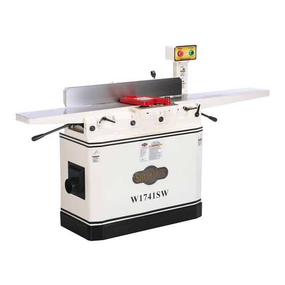
MODEL W1741W/W1741SW
8" JOINTER
OWNER'S MANUAL
(FOR MODELS MANUFACTURED SINCE 10/15)
Phone: (360) 734-3482 • Online Technical Support: techsupport@woodstockint.com
COPYRIGHT © FEBRUARY, 2016 BY WOODSTOCK INTERNATIONAL, INC.
WARNING: NO PORTION OF THIS MANUAL MAY BE REPRODUCED IN ANY SHAPE OR FORM WITHOUT
THE WRITTEN APPROVAL OF WOODSTOCK INTERNATIONAL, INC.
# 17934BL Printed in China
Advertisement
Table of Contents


Need help?
Do you have a question about the W1741W and is the answer not in the manual?
Questions and answers