Table of Contents
Advertisement
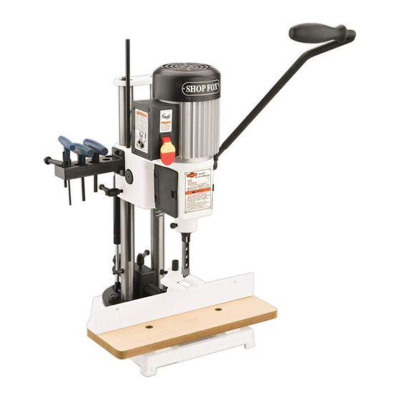
MODEL W1671
Mortising Machine
INSTRUCTION MANUAL
Phone: 1-360-734-3482 • On-Line Technical Support: tech-support@woodstockint.com
COPYRIGHT © 2002 BY WOODSTOCK INTERNATIONAL, INC. REVISED JANUARY, 2012 (TR)
WARNING: NO PORTION OF THIS MANUAL MAY BE REPRODUCED IN ANY SHAPE OR FORM WITHOUT
THE WRITTEN APPROVAL OF WOODSTOCK INTERNATIONAL, INC.
Printed in China
Advertisement
Table of Contents

Related Manuals for Shop fox W1671


Summary of Contents for Shop fox W1671
-
Page 1: Instruction Manual
MODEL W1671 Mortising Machine INSTRUCTION MANUAL Phone: 1-360-734-3482 • On-Line Technical Support: tech-support@woodstockint.com COPYRIGHT © 2002 BY WOODSTOCK INTERNATIONAL, INC. REVISED JANUARY, 2012 (TR) WARNING: NO PORTION OF THIS MANUAL MAY BE REPRODUCED IN ANY SHAPE OR FORM WITHOUT THE WRITTEN APPROVAL OF WOODSTOCK INTERNATIONAL, INC. - Page 2 ����������������������������������������������������������������������� �������������������������������������������������������������� ���������������������������������������������������������������������� �������������������������������������������������������������������� ������������������������ ����������������������������������������������������������������������� ������������������������������������������������������������������������ ������������������������������������������������������������������� ����������������������������������������������������������������� ���������������������������������������������������������������������� ����������������������������������������������� ���������������������������������������������������������������� �������������������������������������������������������������������� ������� �������������������������������������������������������������������� ����������������������������������������������������������������������� ���������������������������������������������������������������������� ������������������������������������� �� ���������������������������� �� ������������������������������������������������������������������ �� ���������������������������������������������������� ������������������������������������������������������������������ ������������������������������������������������������������������ �������������������������������������������������������������������� ��������������������������������������������������������������������� ��������������������������...
-
Page 3: Table Of Contents
Table Of Contents PAGE INTRODUCTION ................2 ABOUT YOUR NEW MORTISING MACHINE ........... 2 WOODSTOCK SERVICE AND SUPPORT ..........2 WARRANTY, RETURNS AND SPECIFICATIONS ........3 SAFETY ..................4 STANDARD SAFETY INSTRUCTIONS ..........4-5 MORTISING MACHINE SAFETY ............5 ELECTRICAL REQUIREMENTS ............6 AVOIDING POTENTIAL INJURIES ............ -
Page 4: Introduction
" drill chuck, a quick-setting handle, an adjustable depth stop and a reliable rack and pinion elevation system. Combined with a ⁄ H.P. motor, a safety switch with removable key and a cord set, the Shop Fox Mortising Machine will give years of satisfying ® use. -
Page 5: Warranty, Returns And Specifications
Woodstock International, Inc. Woodstock International, Inc. will repair or replace, at its expense and at its option, the SHOP FOX ® machine or machine part which in normal use has proven to be defective, provided that the original... -
Page 6: Safety
SAFETY FIRST! READ MANUAL BEFORE OPERATING MACHINE FAILURE TO FOLLOW INSTRUCTIONS BELOW WILL RESULT IN PERSONAL INJURY Indicates an imminently hazardous situation which, if not avoided, WILL result in death or serious injury. Indicates a potentially hazardous situation which, if not avoided, COULD result in death or serious injury. -
Page 7: Mortising Machine Safety
14. Wear proper apparel. Do not wear loose clothing, neck ties, gloves, jewelry, etc. 15. Remove adjusting keys and wrenches. Before turning the machine on, make it a habit to check that all adjusting keys and wrenches have been removed. 16. -
Page 8: Electrical Requirements
•Do not use cords in need of repair Grounding This machine must be grounded! See Figure 1. The electrical cord for the Model W1671 is sup- plied with a 3 prong plug. If your outlet does not accommodate a ground pin, have it replaced by a qualified electrician or have an appropriate adapter installed and grounded properly. -
Page 9: Avoiding Potential Injuries
AVOIDING POTENTIAL INJURIES Figure 2. Unplug before changing chisels. Figure 3. Always clamp workpiece. Fig. 4. Secure depth stop before removing gas spring. Figure 5. Remove safety key when not in use. Figure 6. Never place hands under chisel. Fig. 6A. Secure depth stop before adjusting quick-set handle above. -
Page 10: Assembly Instructions
ASSEMBLY INSTRUCTIONS Figure 7. Components laid out for identification. The following is a description of the components shipped with the Shop Fox W1671 Mortising Machine. It ® is recommended that all the parts be laid out in a similar fashion to those in Figure 7. This will help in identification before beginning assembly. -
Page 11: Mounting
While the main mortising assembly of the Shop Fox W1671 Mortising Machine is assembled at the fac- ® tory, other components require assembly. The following is the recommended sequence best suited for final assembly. TOOLS REQUIRED: You will need the 4, 5 & 6mm Allen wrenches (supplied), a hand drill, a ⁄... -
Page 12: Mounting
Mounting, Cont. 1. Plan the placement of the mortiser. Take measurements of the base and layout a pen- cil drawing for the best location on the work bench. See Figure 9. The Mortiser represents a heavy load that must be lifted from the bottom. -
Page 13: Hand Lever
Hand Lever Clutch Position depth stop to touch table and secure with lock knob before Shouldered attaching hand lever. Bolt The head may drop sud- denly causing injury. Attaching the hand lever requires the use of the 4 and 5mm Allen wrenches supplied. -
Page 14: Gas Spring
Gas Spring The gas spring can be secured to 3 different locations along the side or back of the left col- umn. Each location offers a different range of motion for the mortising head. In the instruc- tions below, we will cover only the side loca- tion. -
Page 15: Work Table
Work Table 1. Secure the wooden work table with the 2 head screws provided. See Figure Phillips ® Figure 14. Work table secured with screws. Fence 1. The fence comes with a micro-adjustable stop attached to the fence support rod, which retains a spring. -
Page 16: Hold Down
Hold Down The hold down acts as a clamp, holding the workpiece to the table surface. This helps to keep the workpiece from raising when extract- ing the chisel after a cut is made. The hold down must be used. 1. -
Page 17: Installing Chisels
Installing Chisels Always unplug the mor- Select the size needed for your project and fol- tising machine before low the instructions below. changing chisels. Failure to do this may result in 1. Support the head with the hand lever serious personal injury. and unlock the depth stop lock knob. -
Page 18: Adjustments
ADJUSTMENTS Gas Spring Locations The gas spring can be positioned in 1 of 3 loca- tions to allow clearance for different board thicknesses or to mortise a board on edge. To determine which setting to use, look at the chart in Figure 21 and find the board thickness that most closely fits your workpiece. -
Page 19: Gas Spring Placement
Gas Spring Placement Swinging the handle out will cause the head casting to fall when the gas spring is removed. The gas spring supports the weight of the head casting and the hand lever regulates its height. However, if the handle is pulled while the gas spring is removed the head will drop suddenly. -
Page 20: Pivot Feature
Pivot Feature The head and column assembly can be adjusted for mortising off of the base. This will allow the mortising machine to accommodate a larger workpiece than those previously listed. To change the position of the head and column assembly: 1. -
Page 21: Wider Stock
5. Place the workpiece against the fence and position the fence so the chisel is near the penciled in marks. Lock the fence. 6. Loosen the setscrew holding the micro adjust- ment block on the fence mounting rod and move the block until the screw fits into the back of the support block. -
Page 22: Operations
OPERATIONS Test Run Once assembly is complete and adjustments are done to your satisfaction, you are ready to test run the machine. Always wear safety glass- es when operating this Mortising Machine. Failure to comply may result in serious personal injury. Make sure the starting switch is off. - Page 23 the head is lowered so the chisel rests on the workpiece. The depth stop rod is adjusted using a measuring tape, to the desired depth. Figure 32 shows the chisel being lowered until the chisel is even with a depth line on the workpiece.
-
Page 24: Maintenance
Since all bearings are sealed and permanently Regular periodic maintenance on your Model lubricated, simply leave them alone until they W1671 Mortising Machine will ensure its opti- need to be replaced. Do not lubricate them. mum performance. Make a habit of inspecting the machine each time you use it. -
Page 25: Closure
General Information. The specifications, The Model W1671 was specifically designed for drawings, and photographs illustrated in this manual represent the Model W1671 as supplied when the manual was prepared. -
Page 26: Parts Breakdown And Parts Lists
29A-1 19 20 56-1... - Page 27 REF PART # DESCRIPTION REF PART # DESCRIPTION X1671001B MOTOR XPW16 FLAT WASHER 9⁄16" X1671002B CHUCK JT MOUNT XPSB13M CAP SCREW M10-1.5 X 25 X1671003 CHUCK KEY XPLW04M LOCK WASHER 8MM X1671004 HEAD CASTING X1671047 TABLE X1671005 LABEL XPFH21M FLAT HD SCR M8-1.25 X 25 XPSB14M CAP SCREW M8-1.25 X 20 X1671049...
-
Page 28: Your Notes
Your Notes:... - Page 29 City ____________________________________________________________________State________Zip_________ Phone Number_______________________E-Mail_________________________________FAX___________________ MODEL # ____________________________________________ SERIAL #____________________________________ The following information is given on a voluntary basis and is strictly confidential. Where did you purchase your Shop Fox machine? How many Shop Fox machines do you own? _____________ ®...
- Page 30 FOLD ALONG DOTTED LINE Place Stamp Here WOODSTOCK INTERNATIONAL, INC. P.O. BOX 2309 BELLINGHAM, WA 98227-2309 FOLD ALONG DOTTED LINE TAPE ALONG EDGES--PLEASE DO NOT STAPLE...
- Page 32 High Quality Machines and Tools Woodstock International, Inc. carries thousands of products designed to meet the needs of today's woodworkers and metalworkers. Ask your dealer about these fine products:...
Need help?
Do you have a question about the W1671 and is the answer not in the manual?
Questions and answers