Table of Contents
Advertisement
Quick Links
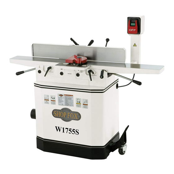
Model W1755S
***IMPORTANT UPDATE***
Applies to Models Mfd. Since 04/15
and Manual Insert Revised 05/08
Phone #: (360) 734-3482 • Tech Support: tech-support@shopfox.biz • Web: www.shopfox.biz
We made the following changes to this machine since the manual insert was printed:
•
Changed spiral cutterhead and indexable inserts.
Aside from the information contained in this update, all other content in the owner's manual is
applicable and MUST be read and understood for your own safety.
IMPORTANT: Keep this update with the owner's manual for future reference. If you have any further
questions, contact our Technical Support.
Revised Parts
169
163
168
167
162V2
REF
PART #
DESCRIPTION
162V2
X1755S162V2
SPIRAL CUTTERHEAD V2.04.15
164V2
X1755S164V2
INDEXABLE INSERT 14 X 14 X 2 V2.04.15
COPYRIGHT © SEPTEMBER, 2015 BY WOODSTOCK INTERNATIONAL, INC.
WARNING: NO PORTION OF THIS MANUAL MAY BE REPRODUCED IN ANY SHAPE OR FORM WITHOUT
#17656MN
READ THIS FIRST
159
164V2
166
THE WRITTEN APPROVAL OF WOODSTOCK INTERNATIONAL, INC.
158
Printed in China
Advertisement
Table of Contents

Related Manuals for Shop fox W1755S


Summary of Contents for Shop fox W1755S
- Page 1 READ THIS FIRST Model W1755S ***IMPORTANT UPDATE*** Applies to Models Mfd. Since 04/15 and Manual Insert Revised 05/08 Phone #: (360) 734-3482 • Tech Support: tech-support@shopfox.biz • Web: www.shopfox.biz We made the following changes to this machine since the manual insert was printed: •...
- Page 2 309V2 X1755309V2 MACHINE ID LABEL CSA V2.07.12 (W1755) 28-6 X1755028-6 R CAPACITOR 40M 250V 309V2 X1755S309V2 MACHINE ID LABEL CSA V2.07.12 (W1755S) 28-7 X1755028-7 MOTOR JUNCTION BOX COPYRIGHT © AUGUST, 2012 BY WOODSTOCK INTERNATIONAL, INC. WARNING: NO PORTION OF THIS MANUAL MAY BE REPRODUCED IN ANY SHAPE OR FORM WITHOUT THE WRITTEN APPROVAL OF WOODSTOCK INTERNATIONAL, INC.
- Page 3 Model W1755/W1755S (Mfg. Since 7/12) SAFETY SAFETY For Your Own Safety, Read Manual Before Operating Machine The purpose of safety symbols is to attract your attention to possible hazardous conditions. This manual uses a series of symbols and signal words intended to convey the level of importance of the safety messages.
- Page 4 Model W1755/W1755S (Mfg. Since 7/12) WEARING PROPER APPAREL. Do not wear FORCING MACHINERY. Do not force machine. It clothing, apparel, or jewelry that can become will do the job safer and better at the rate for entangled in moving parts. Always tie back which it was designed.
- Page 5 Model W1755/W1755S (Mfg. Since 7/12) Additional Safety for Jointers JOINTER INJURY RISKS. Familiarize yourself with INSPECTING STOCK. To reduce the risk of the main injury risks associated with jointers— kickback injuries or machine damage, always use common sense and good judgement thoroughly inspect and prepare the workpiece to reduce your risk of injury.
- Page 6 Model W1755/W1755S (Mfg. Since 7/12) ELECTRICAL Circuit Requirements This machine must be connected to the correct size and type of power supply circuit, or fire or electrical damage may occur. Read through this section to determine if an adequate power supply circuit is available. If a correct circuit is not available, a qualified electrician MUST install one before you can connect the machine to power.
- Page 7 Model W1755/W1755S (Mfg. Since 7/12) Grounding Requirements This machine MUST be grounded. In the event of certain types of malfunctions or breakdowns, grounding provides a path of least resistance for electric current to travel—in order to reduce the risk of electric shock.
- Page 8 Wire Nut (14 AWG x 3) ........1 Re-Connect • Plug 6-15 ............1 Tighten and Tighten To convert the Model W1755/W1755S to 240V: Re-Connect and Tighten 1. DISCONNECT MACHINE FROM POWER! 2. Cut off the included plug. 3. Open the motor junction box, then remove the wire nuts indicated in Figure 3.
- Page 9 Model W1755/W1755S (Mfg. Since 7/12) 120V Wiring Diagram 120 VAC MOTOR 5-15 Plug (Pre-wired) SWITCH (viewed from behind) 240V Wiring Diagram WARNING! SHOCK HAZARD! Disconnect power before working on wiring. MOTOR (Rewired) 240 VAC SWITCH (viewed from behind)
- Page 10 Phone #: (360) 734-3482 • Online Tech Support: tech-support@shopfox.biz • Web: www.shopfox.biz The Model W1755S is the same as the Model W1755, except it has a spiral cutterhead. Besides the data sheet and parts in this insert, the content in the Model W1755 owner's manual is the same for both machines.
- Page 11 Switch Type..........ON/OFF Push Button Switch w/Large Shut‐Off Paddle Motors Main Horsepower....................1.5 HP Phase....................Single‐Phase Amps....................15A/7.5A Speed....................3450 RPM Type................. TEFC Capacitor‐Start Induction Power Transfer ..................Belt Drive Bearings............... Shielded & Permanently Lubricated Model W1755S Machine Specifications, Page 1 of 3...
- Page 12 Cabinet..................Pre‐formed Steel Fence Assembly..................Cast Iron Guard....................Aluminum Table................Precision Ground Cast Iron Paint Type/Finish................Powder Coated Other Information Number of Dust Ports..................1 Dust Port Size....................4 in. Mobile Base..................... Built‐In Model W1755S Machine Specifications, Page 2 of 3...
- Page 13 W1755S 6" Parallelogram Jointer with Spiral Cutterhead Stand Breakdown 28-1 28-3 28-2 28-4 28-7 28-5 28-6...
- Page 14 W1755S 6" Parallelogram Jointer with Spiral Cutterhead Stand Parts List PART # DESCRIPTION PART # DESCRIPTION X1755S001 FLAT WASHER 5MM 28-3 X1755S028-3 CAPACITOR COVER X1755S002 PANEL 28-4 X1755S028-4 S CAPACITOR 300M 125V X1755S003 FLANGE SCREW M6-1 X 12 28-5 X1755S028-5 CAPACITOR COVER...
- Page 15 W1755S 6" Parallelogram Jointer with Spiral Cutterhead Jointer Breakdown...
- Page 16 W1755S 6" Parallelogram Jointer with Spiral Cutterhead Jointer Parts List PART # DESCRIPTION PART # DESCRIPTION X1755S101 LEVER KNOB X1755S156 CAP SCREW M8-1.25 X 80 X1755S102 STUD X1755S157 LOCK WASHER 8MM X1755S103 BUSHING X1755S158 BEARING BLOCK LEFT X1755S104 SHAFT X1755S159...
- Page 17 W1755S 6" Parallelogram Jointer with Spiral Cutterhead Jointer Parts List, cont. PART # DESCRIPTION PART # DESCRIPTION X1755S213 LEVER X1755S225 HEX WRENCH 8MM X1755S214 HANDLE X1755S229 SWITCH PEDESTAL X1755S215 CAP SCREW M8-1.25 X 40 X1755S230 CAP SCREW M8-1.25 X 25...
- Page 18 309V2 X1755309V2 MACHINE ID LABEL CSA V2.07.12 (W1755) 28-6 X1755028-6 R CAPACITOR 40M 250V 309V2 X1755S309V2 MACHINE ID LABEL CSA V2.07.12 (W1755S) 28-7 X1755028-7 MOTOR JUNCTION BOX COPYRIGHT © AUGUST, 2012 BY WOODSTOCK INTERNATIONAL, INC. WARNING: NO PORTION OF THIS MANUAL MAY BE REPRODUCED IN ANY SHAPE OR FORM WITHOUT THE WRITTEN APPROVAL OF WOODSTOCK INTERNATIONAL, INC.
- Page 19 Model W1755/W1755S (Mfg. Since 7/12) SAFETY SAFETY For Your Own Safety, Read Manual Before Operating Machine The purpose of safety symbols is to attract your attention to possible hazardous conditions. This manual uses a series of symbols and signal words intended to convey the level of importance of the safety messages.
- Page 20 Model W1755/W1755S (Mfg. Since 7/12) WEARING PROPER APPAREL. Do not wear FORCING MACHINERY. Do not force machine. It clothing, apparel, or jewelry that can become will do the job safer and better at the rate for entangled in moving parts. Always tie back which it was designed.
- Page 21 Model W1755/W1755S (Mfg. Since 7/12) Additional Safety for Jointers JOINTER INJURY RISKS. Familiarize yourself with INSPECTING STOCK. To reduce the risk of the main injury risks associated with jointers— kickback injuries or machine damage, always use common sense and good judgement thoroughly inspect and prepare the workpiece to reduce your risk of injury.
- Page 22 Model W1755/W1755S (Mfg. Since 7/12) ELECTRICAL Circuit Requirements This machine must be connected to the correct size and type of power supply circuit, or fire or electrical damage may occur. Read through this section to determine if an adequate power supply circuit is available. If a correct circuit is not available, a qualified electrician MUST install one before you can connect the machine to power.
- Page 23 Model W1755/W1755S (Mfg. Since 7/12) Grounding Requirements This machine MUST be grounded. In the event of certain types of malfunctions or breakdowns, grounding provides a path of least resistance for electric current to travel—in order to reduce the risk of electric shock.
- Page 24 Wire Nut (14 AWG x 3) ........1 Re-Connect • Plug 6-15 ............1 Tighten and Tighten To convert the Model W1755/W1755S to 240V: Re-Connect and Tighten 1. DISCONNECT MACHINE FROM POWER! 2. Cut off the included plug. 3. Open the motor junction box, then remove the wire nuts indicated in Figure 3.
- Page 25 Model W1755/W1755S (Mfg. Since 7/12) 120V Wiring Diagram 120 VAC MOTOR 5-15 Plug (Pre-wired) SWITCH (viewed from behind) 240V Wiring Diagram WARNING! SHOCK HAZARD! Disconnect power before working on wiring. MOTOR (Rewired) 240 VAC SWITCH (viewed from behind)
- Page 26 MODEL W1755 6" PARALLELOGRAM JOINTER OWNER'S MANUAL Phone: (360) 734-3482 • On-Line Technical Support: tech-support@shopfox.biz COPYRIGHT © MARCH, 2007 BY WOODSTOCK INTERNATIONAL, INC. REVISED APRIL, 2007. WARNING: NO PORTION OF THIS MANUAL MAY BE REPRODUCED IN ANY SHAPE OR FORM WITHOUT THE WRITTEN APPROVAL OF WOODSTOCK INTERNATIONAL, INC.
- Page 27 ����������������������������������������������������������������������� �������������������������������������������������������������� ���������������������������������������������������������������������� �������������������������������������������������������������������� ������������������������ ����������������������������������������������������������������������� ������������������������������������������������������������������������ ������������������������������������������������������������������� ����������������������������������������������������������������� ���������������������������������������������������������������������� ����������������������������������������������� ���������������������������������������������������������������� �������������������������������������������������������������������� ������� �������������������������������������������������������������������� ����������������������������������������������������������������������� ���������������������������������������������������������������������� ������������������������������������� �� ���������������������������� �� ������������������������������������������������������������������ �� ���������������������������������������������������� ������������������������������������������������������������������ ������������������������������������������������������������������ �������������������������������������������������������������������� ��������������������������������������������������������������������� ��������������������������...
-
Page 28: Table Of Contents
Table of Contents INTRODUCTION ........2 SERVICE ..........28 Woodstock Technical Support ....2 General ...........28 Controls and Features ......4 Inspecting Knives ........28 Adjusting/Replacing Knives ....29 SAFETY ..........5 Checking/Adjusting Table Parallelism ..32 Standard Safety Instructions ....5 Setting Outfeed Table Height ....35 Additional Safety Instructions for Jointers ... -
Page 29: Introduction
W1755 6" Parallelogram Jointer INTRODUCTION Woodstock Technical Support Your new SHOP FOX 6" Parallelogram Jointer has been specially designed to provide many years of ® trouble-free service. Close attention to detail, ruggedly built parts and a rigid quality control program assure safe and reliable operation. - Page 30 W1755 6" Parallelogram Jointer MACHINE SPECIFICATIONS Phone #: (360) 734-3482 • Online Tech Support: tech-support@shopfox.biz • Web: www.shopfox.biz MODEL W1755 6" PARALLELOGRAM JOINTER Motor Type ..................TEFC Capacitor Start Induction Horsepower ......................1 ⁄ Phase / Voltage .................. Single-Phase / 110V/220V Amps ........................
-
Page 31: Controls And Features
W1755 6" Parallelogram Jointer Controls and Features A. Outfeed Table B. Fence C. Cutterhead Guard D. ON/OFF Switch E. Infeed Table F. Infeed Table Adjustment Lever G. Cutting Depth Scale H. Infeed Table Lock Mobile Base Lock Pedal Outfeed Table Lock K. -
Page 32: Safety
W1755 6" Parallelogram Jointer SAFETY READ MANUAL BEFORE OPERATING MACHINE. FAILURE TO FOLLOW INSTRUCTIONS BELOW WILL RESULT IN PERSONAL INJURY. Indicates an imminently hazardous situation which, if not avoided, WILL result in death or serious injury. Indicates a potentially hazardous situation which, if not avoided, COULD result in death or serious injury. - Page 33 W1755 6" Parallelogram Jointer 10. NEVER LEAVE WHEN MACHINE IS RUNNING. Turn power OFF and allow all moving parts to come to a complete stop before leaving machine unattended. 11. DO NOT USE IN DANGEROUS ENVIRONMENTS. DO NOT use machinery in damp, wet locations, or where any flammable or noxious fumes may exist.
-
Page 34: Additional Safety Instructions For Jointers
W1755 6" Parallelogram Jointer Additional Safety Instructions for Jointers READ and understand this USE this and other machinery with caution entire instruction manual and respect. Always consider safety first, before using this machine. as it applies to your individual working Serious personal injury conditions. -
Page 35: Avoiding Potential Injuries
W1755 6" Parallelogram Jointer Avoiding Potential Injuries Figure 1. Correct operator and workpiece position, guard is in place, and push blocks are being used. Figure 4. Never stand directly behind the Figure 2. Never surface plane without push blocks! workpiece! Figure 5. -
Page 36: Electrical
W1755 6" Parallelogram Jointer ELECTRICAL 110V/220V Operation The Model W1755 is prewired for 110V operation, but you can rewire it for 220V operation (refer to the wir- ing diagram on Page 41). We recommend connecting this machine to a dedicated circuit with a verified ground, using the circuit size given below. -
Page 37: Setup
W1755 6" Parallelogram Jointer SETUP Unpacking SHOP FOX READ and understand this Model W1755 has been carefully pack- ® aged for safe transporting. If you notice the machine has entire instruction manual SHOP been damaged, please contact your authorized before using this machine. -
Page 38: Inventory
W1755 6" Parallelogram Jointer Inventory The following is a description of the items shipped with SHOP FOX Model W1755. ® Note: If you can't find an item on this list, check the mounting location on the machine or examine the pack- aging materials carefully. -
Page 39: Machine Placement
W1755 6" Parallelogram Jointer Machine Placement Cleaning Machine • Floor Load: This machine distributes a The table and other unpainted parts of your heavy load in a small footprint. Some Jointer are coated with a waxy grease that residential floors may require additional protects them from corrosion during shipment. -
Page 40: Assembly
W1755 6" Parallelogram Jointer Assembly To assemble the jointer, do these steps: 1. Carefully lay the stand on its side so you can access the underside. 2. Use the M8-1.25 x 50 hex bolt and 8mm flat washer to bolt the wheel assembly to the stand, as shown in Figure 9. - Page 41 W1755 6" Parallelogram Jointer 7. Loosen the motor bracket bolts shown by the black arrows in Figure 12. 8. Put the V-belt on the motor pulley, then roll it onto the cutterhead pulley, as shown in Figure 13. 9. Check the alignment of the pulleys to make sure the V-belt is straight up and down.
- Page 42 W1755 6" Parallelogram Jointer 15. Install the belt guard with the two M6-1 x 10 flange bolts, M6-1 hex nuts, and 6mm flat washers, as Belt Guard shown in Figure 15. The belt guard MUST be installed or the moving V- belt will be exposed, creating an entanglement haz- ard at the back of the jointer.
- Page 43 W1755 6" Parallelogram Jointer 21. Attach the carriage to the back of the jointer with the M10-1.5 x 30 cap screw on the infeed side, the Paper M10-1.5 x 50 cap screw on the outfeed side, and two 10mm flat washers. Leave the cap screws loose for now.
-
Page 44: Dust Collection
W1755 6" Parallelogram Jointer 29. Test that the cutterhead guard is working correctly by pulling it back and letting go. The cutterhead guard should quickly spring back over the cutterhead when you do this. — If the guard does not quickly spring back over Set Screw the cutterhead when you perform this test, then remove it and repeat Steps 27–29. -
Page 45: Test Run
W1755 6" Parallelogram Jointer Test Run Complete this process once you have familiarized yourself with all instructions in this manual. To test run the jointer, do these steps: 1. Read the entire owner's manual first to make sure you are familiar with the safety and operation con- trols of this machine! Projectiles thrown from the machine 2. -
Page 46: Operations
W1755 6" Parallelogram Jointer OPERATIONS General The Model W1755 will perform many types of operations that are beyond the scope of this manual. Many of these operations can be dangerous or deadly if performed incorrectly. The instructions in this section are written with the understanding that the operator has the necessary knowl- edge and skills to operate this machine. -
Page 47: Basic Controls
W1755 6" Parallelogram Jointer Basic Controls This section covers the basic controls used during routine START Button operations. ON/OFF Switch (Figure 26): Starts and stops the motor. After the OFF paddle is pushed, the switch may need to be reset before the next operation by lifting the paddle and fully depressing the STOP button. -
Page 48: Stock Inspection & Requirements
W1755 6" Parallelogram Jointer Stock Inspection & Requirements Here are some rules to follow when choosing and jointing stock: ������� �������������� �������� DO NOT joint or surface plane stock that contains • ������������� ������������ loose knots. Injury to the operator or damage to the ����������... -
Page 49: Squaring Stock
W1755 6" Parallelogram Jointer Squaring Stock Squaring stock involves four steps performed in the order below: 1. Surface Plane on the Jointer: The concave face of the workpiece is surface planed flat with the jointer (Figure 32). 2. Surface Plane on a Thickness Planer: The opposite Figure 32. -
Page 50: Surface Planing
W1755 6" Parallelogram Jointer Surface Planing The purpose of surface planing on the jointer is to make one flat face on a piece of stock (see Figures 36 & 37) to prepare it for surface planing on a thickness planer. NOTICE If you are not experienced with a jointer, set the depth of cut to 0", and practice feeding the... -
Page 51: Edge Jointing
W1755 6" Parallelogram Jointer Edge Jointing The purpose of edge jointing is to produce a finished, flat-edged surface (see Figures 38 & 39) that is suitable for joinery or finishing. It is also a necessary step when squaring rough or warped stock. NOTICE If you are not experienced with a jointer, set the depth of cut to 0", and practice feeding the... -
Page 52: Bevel Cutting
W1755 6" Parallelogram Jointer Bevel Cutting The purpose of bevel cutting is to cut a specific angle NOTICE into the edge of a workpiece (see Figures 40 & 41). If you are not experienced with a The Model W1755 has preset fence stops at 45˚ inward, jointer, set the depth of cut to 0", and 90˚... -
Page 53: Rabbet Cutting
W1755 6" Parallelogram Jointer Rabbet Cutting Rabbet cuts remove a section of the workpiece edge (see NOTICE Figures 42 & 43). When combined with another rabbet cut edge, the rabbet joints create a simple, yet strong If you are not experienced with a method of joining stock. -
Page 54: Maintenance
W1755 6" Parallelogram Jointer MAINTENANCE General SHOP FOX Regular periodic maintenance on your ® Model W1755 will ensure its optimum performance. Make a habit of inspecting your machine each time you use it. Check for the following conditions and repair or replace when necessary: •... -
Page 55: Service
W1755 6" Parallelogram Jointer SERVICE General This section covers the most common service adjustments or procedures that may need to be made during the life of your machine. If you require additional machine service not included in this section, please contact Woodstock International Technical Support at (360) 734-3482 or send e-mail to: tech-support@shopfox.biz. -
Page 56: Adjusting/Replacing Knives
W1755 6" Parallelogram Jointer Adjusting/Replacing Knives Setting the knives correctly is crucial to the proper oper- ation of the jointer and is very important in keeping the knives sharp. If one knife is higher than the others, it will do the majority of the work, and thus, dull much faster than the others. - Page 57 W1755 6" Parallelogram Jointer The Model W1755 comes with both jack screws and springs inside the cutterhead to provide two options for adjusting the knives (see Figure 46). Note: Only one of these options is needed to set the knives—Step 5 gives the details. To adjust/replace the knives, do these steps: 1.
- Page 58 W1755 6" Parallelogram Jointer 7. Adjusting the knife heights: Jack Screws: Using a 3mm hex wrench, find the jack Jack Screw Access Hole screws through the access holes in the cutterhead (Figure 48) and rotate the jack screws to raise or lower the knife.
-
Page 59: Checking/Adjusting Table Parallelism
W1755 6" Parallelogram Jointer Checking/Adjusting Table Parallelism If the tables are not parallel with the cutterhead or each other, then poor cutting results and kickback may occur. Checking Outfeed Table To check the outfeed table parallelism, do these steps: 1. DISCONNECT JOINTER FROM POWER SOURCE! 2. - Page 60 W1755 6" Parallelogram Jointer 3. Place the straightedge halfway across the infeed table and halfway over the outfeed table, and adjust the infeed table even with the outfeed table, as shown in Figure 53. ������������ 4. Place the straightedge in the positions shown in �������������...
- Page 61 W1755 6" Parallelogram Jointer To adjust the table parallelism, do these steps: Location of Stacked Set 1. DISCONNECT JOINTER FROM POWER SOURCE! Screws 2. Remove the cutterhead guard and fence. Eccentric Bushing 3. Place the straightedge on the outfeed table so it hangs over the cutterhead, and lower the outfeed table until the straightedge just touches the cutterhead body, as shown in Figure 51.
-
Page 62: Setting Outfeed Table Height
W1755 6" Parallelogram Jointer Setting Outfeed Table Height The outfeed table height must be even with the cutterhead knives at top dead center. If the outfeed table is set too low, there will be snipe. If the outfeed table is set too high, the workpiece will hit the edge of the ��������... -
Page 63: Setting Infeed Table Height
W1755 6" Parallelogram Jointer Setting Infeed Table Height The infeed table on the Model W1755 has positive stop Jam Nuts bolts that, when properly set up, allow the operator to quickly adjust the infeed table between finish/final cuts Top Height (top height) and shaping/heavy cuts (bottom height). -
Page 64: Setting Fence Stops
W1755 6" Parallelogram Jointer Setting Fence Stops The fence stops simplify the task of adjusting the fence to 45˚ inward, 90˚ , and 45˚ outward (135˚). Positive To set the 45˚ inward fence stop, do these steps: Stop 1. Tilt the fence approximately 45° inward (Figure 60) onto the positive stop bolts, using a 45°... -
Page 65: V-Belt Replacement
W1755 6" Parallelogram Jointer V-Belt Replacement Inspect the V-belt closely; if you notice fraying, cracking, glazing, or any other damage, replace the belt. A worn or damaged V-belt will not provide optimum power transmis- sion from the motor to the cutterhead. Overly loose V-belts can slip on the pulleys and burn up or cause poor machine performance. -
Page 66: Pulley Alignment
W1755 6" Parallelogram Jointer Pulley Alignment Pulley alignment is another important factor in power transmission and belt life. The pulleys should be parallel to each other and in the same plane (coplanar) for opti- mum performance. ���������� ������ Each pulley can be adjusted by loosening the motor ���������... -
Page 67: Electrical Components
W1755 6" Parallelogram Jointer Electrical Components Figure 69. Motor wired for 110V. Figure 71. Motor wired for 220V. ON Switch OFF Switch Figure 70. ON/OFF Switch. Figure 72. Motor capacitors. -40-... -
Page 68: Wiring Diagram
Wiring Diagram W1755 6" Parallelogram Jointer 110V Wiring Diagram �������� ����� ������� ���������� ����� ������ ������� �� ������� ������� See Figure 72 ��� ����� ��� ����� ��� ��� ��������� ��������� ������ ����� ������ ������ ������ � � � � � �... -
Page 69: Troubleshooting
W1755 6" Parallelogram Jointer Troubleshooting This section covers the most common problems and corrections with this type of machine. WARNING! DO NOT make any adjustments until power is disconnected and moving parts have come to a complete stop! Motor & Electrical PROBLEM POSSIBLE CAUSE CORRECTIVE ACTION... - Page 70 W1755 6" Parallelogram Jointer Cutting PROBLEM POSSIBLE CAUSE CORRECTIVE ACTION Excessive snipe (gouge in 1. Outfeed table is set too low. 1. Align outfeed table at top dead center of the the end of the board that cutterhead knives (Page 35). is uneven with the rest of 2.
-
Page 71: Parts
W1755 6" Parallelogram Jointer PARTS Stand Breakdown � � �� � ���� � ���� � ���� ���� �� � ���� � ���� ���� �� �� �� �� �� �� �� �� � �� �� � �� �� �� �� �� ��... -
Page 72: Stand Parts List
W1755 6" Parallelogram Jointer Stand Parts List PART�# DESCRIPTION PART�# DESCRIPTION XPW02M FLAT�WASHER�5MM 28-3 X1755028-3 CAPACITOR�COVER X1755002 PANEL 28-4 X1755028-4 CAPACITOR�300MFD�125VAC XPFS02M FLANGE�SCREW�M6-1�X�12 28-5 X1755028-5 CAPACITOR�COVER X1755004 BELT�GUARD 28-6 X1755028-6 CAPACITOR�40MFD�250VAC X1755005 CABINET�STAND 28-7 X1755028-7 WIRING�BOX XPW03M FLAT�WASHER�6MM XPSB31M CAP�SCREW�M8-1.25�X�25 XPN01M HEX�NUT�M6-1 XPLW04M... -
Page 73: Jointer Breakdown
W1755 6" Parallelogram Jointer Jointer Breakdown ��� ��� ��� ��� ��� ��� ��� ��� ��� ��� ��� ��� ��� ��� ��� ��� ��� ��� ��� ��� ��� ��� ��� ��� ��� ��� ��� ��� ��� ��� ��� ��� ��� ��� ���... -
Page 74: Jointer Parts List
W1755 6" Parallelogram Jointer Jointer Parts List PART�# DESCRIPTION PART�# DESCRIPTION X1755101 LEVER�KNOB X1755150 TABLE�RH X1755102 STUD X1755151 TABLE�SHAFT X1755103 BUSHING X1755152 RABBETING�EXTENSION�TABLE X1755104 SHAFT XPSB02M CAP�SCREW�M6-1�X�20 XPSS11M SET�SCREW�M6-1�X�16 X1755154 CHIP�DEFLECTOR XPSS14M SET�SCREW�M8-1.25�X�12 XPSB33M CAP�SCREW�M5-.8�X�12 X1755107 CARRIAGE XPSB148M CAP�SCREW�M8-1.25�X�80 XPN01M HEX�NUT�M6-1 XPLW04M LOCK�WASHER�8MM... - Page 75 W1755 6" Parallelogram Jointer Jointer Parts List PART�# DESCRIPTION PART�# DESCRIPTION XPB02M HEX�BOLT�M6-1�X�12 X1755220 OPEN�END�WRENCH�12/14MM XPW01M FLAT�WASHER�8MM XPAW02.5M HEX�WRENCH�2.5MM X1755202 ADJUSTABLE�HANDLE XPAW04M HEX�WRENCH�4MM X1755203 ECCENTRIC�BUSHING XPAW05M HEX�WRENCH�5MM X1755204 TABLE�SHAFT XPAW06M HEX�WRENCH�6MM XPSS14M SET�SCREW�M8-1.25�X�12 XPAW08M HEX�WRENCH�8MM X1755206 TABLE�SHAFT XPEC015M E-CLIP�8MM X1755207 POINTER X1755227 KNIFE�GAUGE�BLOCK...
-
Page 76: Labels/Cosmetic Parts
W1755 6" Parallelogram Jointer Labels/Cosmetic Parts Safety labels warn about machine hazards and ways to prevent injury. The owner of this machine MUST maintain the original location and readability of the labels on the machine. If any label is removed or becomes unreadable, REPLACE that label before using the machine again. -
Page 77: Warranty
Warranty SHOP FOX Woodstock International, Inc. warrants all machinery to be free of defects from work- ® manship and materials for a period of two years from the date of original purchase by the original owner. This warranty does not apply to defects due directly or indirectly to misuse, abuse, negligence or accidents, lack of maintenance, or reimbursement of third party expenses incurred. - Page 78 2. How long have you been a woodworker/metalworker? _____ 0-2 Years _____ 2-8 Years ____ 8-20 Years _____ 20+ Years 3. How many of your machines or tools are Shop Fox ® _____ 0-2 _____ 3-5 ____ 6-9 _____ 10+ 4.
- Page 79 FOLD ALONG DOTTED LINE Place Stamp Here WOODSTOCK INTERNATIONAL INC. P.O. BOX 2309 BELLINGHAM, WA 98227-2309 FOLD ALONG DOTTED LINE TAPE ALONG EDGES--PLEASE DO NOT STAPLE...
Need help?
Do you have a question about the W1755S and is the answer not in the manual?
Questions and answers