Advertisement
Quick Links
HOLEMAKER HM40AD
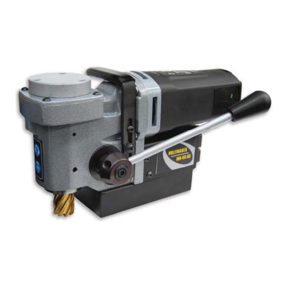
Holemaker Portable Magnetic Drilling Machine
OPERATOR'S MANUAL
OPERATOR'S MANUAL
WARNING!
,
BEFORE USE
ENSURE EVERYONE USING THIS MACHINE READS AND UNDERSTANDS
.
ALL SAFETY AND OPERATING INSTRUCTIONS IN THIS MANUAL
EYE PROTECTION
HEARING PROTECTION
NEVER PLACE
LINE VOLTAGE
BEWARE OF
REQUIRED
REQUIRED
FINGERS NEAR
PRESENT
ROTATING
CUTTING AREA OR
MACHINE PARTS
MACHINE ARBOR
S
r e
a i
# l
D
a
e t
f o
P
r u
h c
a
e s
VER: 1.10
14/08/15
Advertisement

Related Manuals for HOLEMAKER HM40AD


Summary of Contents for HOLEMAKER HM40AD
- Page 1 HOLEMAKER HM40AD Holemaker Portable Magnetic Drilling Machine OPERATOR’S MANUAL OPERATOR’S MANUAL WARNING! BEFORE USE ENSURE EVERYONE USING THIS MACHINE READS AND UNDERSTANDS ALL SAFETY AND OPERATING INSTRUCTIONS IN THIS MANUAL EYE PROTECTION HEARING PROTECTION NEVER PLACE LINE VOLTAGE BEWARE OF...
-
Page 2: Table Of Contents
Holemaker Portable Magnetic Drilling Machine Congratulations on your purchase of a Holemaker portable magnetic drilling machine. Holemaker drilling machines are designed to deliver fast, efficient hole drilling performance in portable applications. DIMENSIONS & SPECIFICATIONS Height 181mm Width 189mm Length (inc. Handle) -
Page 3: Important Safety Instructions
IMPORTANT SAFETY INSTRUCTIONS WARNING! WHEN USING ELECTRIC TOOLS BASIC SAFETY PRECAUTIONS SHOULD ALWAYS BE FOLLOWED TO REDUCE RISK OF FIRE ELECTRIC SHOCK AND PERSONAL INJURY READ AND SAVE ALL INSTRUCTIONS FOR FUTURE REFERENCE. 1. Keep Work Area Clean • Cluttered areas and benches invite injuries. 2. -
Page 4: Important Safety Instructions
IMPORTANT SAFETY INSTRUCTIONS 13. Maintain Tools With Care • Keep tools sharp and clean for better and safer performance. • Follow instructions for lubricating and changing accessories. • Inspect tool cords periodically and if damaged, have repaired by authorized service facility. •... -
Page 5: Grounding Instructions
If the cord or plug is damaged, have it repaired before using. If the plug will not fit the outlet, have a proper outlet installed by a qualified electrician. The Holemaker must be plugged into an appropriate outlet, properly installed and grounded in accordance with all codes and ordinances. -
Page 6: Special Instructions
2. Remove any excessive mill scale or rust from surface to be drilled. 3. When drilling thin materials, it is recommended that you place a steel plate under the work piece and Holemaker magnet area to increase magnetic holding force. - Page 7 Fill coolant reservoir with a water-soluble coolant. Position the Holemaker on the work piece with the pilot pin over the centre of the hole to be cut. Lower cutter/drill to surface of material. coolant flow starts when pilot pin is depressed.
-
Page 8: Basic Troubleshooting
BASIC TROUBLESHOOTING 1. Magnetic base not holding securely • Surface of material being drilled must be free of chips, debris, rust and mill scale. • Does size of cutter exceed machine’s rated capacity? • Check magnet face for unevenness, nicks and burrs. •... -
Page 9: Machine Breakdown
MACHINE BREAKDOWN ITEM PART NUMBER DESCRIPTION SPAD40-01 MAIN BODY ASSEMBLY SPAD40-02 ELECTROMAGNETIC BASE ASSEMBLY SPAD40-03 QUILL ASSEMBLY SPAD40-04 BEVEL GEAR T=39 ASSEMBLY SPAD40-05 GEAR BOX COVER ASSEMBLY SPAD40-06 BEARING NUT HOLDER SPAD40-07 FEED SHAFT HOLDER SPAD40-08 SELF-LUBRICATING SLEEVE 32/26-20-15 SPAD40-09 GEAR Z=32 SPAD40-10 KEY 6x6x16... -
Page 10: Machine Breakdown
MACHINE BREAKDOWN... - Page 11 MAIN BODY ASSEMBLY ITEM PART NUMBER DESCRIPTION SPAD40-01-01 MAIN BODY SPAD40-01-02 BUSHING PERMAGLIDE I SPAD40-01-03 BUSHING PERMAGLIDE II SPAD40-01-04 SOCKET SET SCREW M6 x 8 SPAD40-01-05 PRESSURE SCREW...
- Page 12 QUILL ASSEMBLY ITEM PART NUMBER DESCRIPTION SPAD40-03-01 QUILL CARRIER SPAD40-03-02 SPINDLE SPAD40-03-03 DISTANCE SLEEVE SPAD40-03-04 SPRING SPAD40-03-05 SEAL SPAD40-03-06 PLUNGER SPAD40-03-07 NEEDLE BEARING RHNA303720 SPAD40-03-08 BEARING BALL 6004 2RS SPAD40-03-09 INTERNAL RETAINING RING 19W 3.10 SPAD40-03-10 EXTERNAL RETAINING RING- 20Z 3.11 SPAD40-03-11 INTERNAL RETAINING RING - 42W...
- Page 13 BEVEL GEAR ASSEMBLY ITEM PART NUMBER DESCRIPTION SPAD40-04-01 BEVEL GEAR T=39 ASSY / INCL. SLEEVE SPAD40-04-02 BEARING NUT SPAD40-04-03 BEARING BALL 61805 2RS SPAD40-04-04 EXTERNAL RETAINING RING 25Z TYPE A SPAD40-04-05 INTERNAL RETAINING RING 37W SPAD40-04-06 HEX SET SCREW M5x10...
- Page 14 BEVEL GEAR SLEEVE ASSEMBLY ITEM PART NUMBER DESCRIPTION SPAD40-04-01 BEVEL GEAR T=39 ASSY / INCL. SLEEVE SPAD40-04-02 BEARING NUT SPAD40-04-03 BEARING BALL 61805 2RS SPAD40-04-04 EXTERNAL RETAINING RING 25Z TYPE A SPAD40-04-05 INTERNAL RETAINING RING 37W SPAD40-04-06 HEX SET SCREW M5x10...
- Page 15 GEARBOX COVER ASSEMBLY ITEM PART NUMBER DESCRIPTION SPAD40-05-01 GEAR BOX COVER SPAD40-05-02 JUMPER SPAD40-05-03...
- Page 16 SHAFT ASSEMBLY ITEM PART NUMBER DESCRIPTION SPAD40-04-01 BEVEL GEAR T=39 ASSY / INCL. SLEEVE SPAD40-04-02 BEARING NUT SPAD40-04-03 BEARING BALL 61805 2RS SPAD40-04-04 EXTERNAL RETAINING RING 25Z TYPE A SPAD40-04-05 INTERNAL RETAINING RING 37W SPAD40-04-06 HEX SET SCREW M5x10...
- Page 17 MOTOR ASSEMBLY ITEM PART NUMBER DESCRIPTION 27.1 SPAD40-27-01 MOTOR /230V 27.2 SPAD40-27-02 MOTOR COVER 27.3 SPAD40-27-03 SELF-TAPPING SCREW 5x20...
- Page 18 ELECTRONIC CONTROLLER ASSEMBLY ITEM PART NUMBER DESCRIPTION 32.1 SPAD40-32-01 ELECTRONIC CONTROLLER FRAME 32.2 SPAD40-32-02 START-STOP SWITCH 32.3 SPAD40-32-03 SWITCH, MAGNET HOLEMAKER 32.4 SPAD40-32-04 POWER CORD /230V 32.5 SPAD40-32-05 STRAIN RELIEF NUT 32.6 SPAD40-32-06 SNAP BUSHING LA6 32.7 SPAD40-32-07 ELECTRONIC CONTROLLER SW-30 / 230V 32.8...
- Page 19 WIRING DIAGRAM...
Need help?
Do you have a question about the HM40AD and is the answer not in the manual?
Questions and answers