Advertisement
HOLEMAKER PRO 40
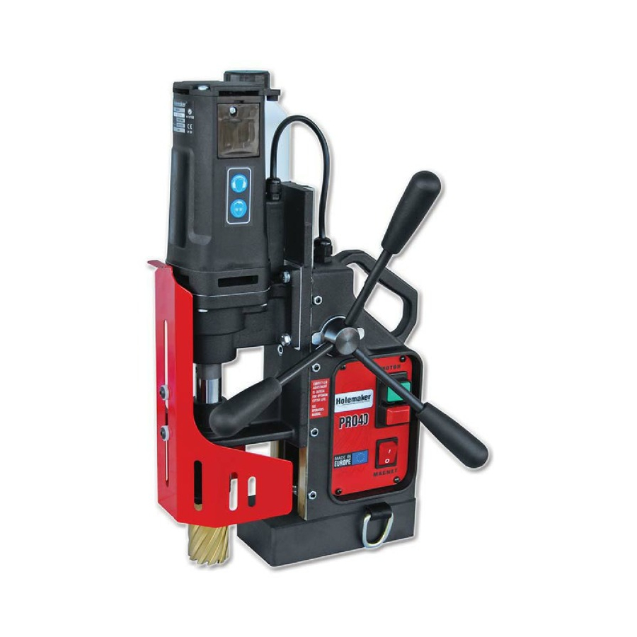
Holemaker Portable Magnetic Drilling Machine
OPERATOR'S MANUAL
WARNING!
,
BEFORE USE
ENSURE EVERYONE USING THIS MACHINE READS AND UNDERSTANDS
.
ALL SAFETY AND OPERATING INSTRUCTIONS IN THIS MANUAL
EYE PROTECTION
HEARING PROTECTION
NEVER PLACE
LINE VOLTAGE
BEWARE OF
REQUIRED
REQUIRED
FINGERS NEAR
PRESENT
ROTATING
CUTTING AREA OR
MACHINE PARTS
MACHINE ARBOR
S
r e
a i
# l
D
a
e t
f o
P
r u
h c
a
e s
Advertisement
Table of Contents

Related Manuals for HOLEMAKER PRO 40


Summary of Contents for HOLEMAKER PRO 40
- Page 1 HOLEMAKER PRO 40 Holemaker Portable Magnetic Drilling Machine OPERATOR’S MANUAL WARNING! BEFORE USE ENSURE EVERYONE USING THIS MACHINE READS AND UNDERSTANDS ALL SAFETY AND OPERATING INSTRUCTIONS IN THIS MANUAL EYE PROTECTION HEARING PROTECTION NEVER PLACE LINE VOLTAGE BEWARE OF REQUIRED...
-
Page 2: Table Of Contents
Holemaker PRO 40 Portable Magnetic Drilling Machine Congratulations on the purchase of your Holemaker Pro 40 portable magnetic drilling machine. Holemaker drilling machines are designed to deliver fast, efficient hole drilling performance in portable applications. TABLE OF CONTENTS Important Safety Instructions ........3 - 4 Power Supply Requirement . -
Page 3: Important Safety Instructions
IMPORTANT SAFETY INSTRUCTIONS WARNING! WHEN USING ELECTRICAL TOOLS BASIC SAFETY PRECAUTIONS SHOULD ALWAYS BE FOLLOWED TO REDUCE RISK OF FIRE ELECTRIC SHOCK AND PERSONAL INJURY READ AND SAVE ALL INSTRUCTIONS FOR FUTURE REFERENCE. 1. Keep Work Area Clean • Cluttered areas and benches increase risk of injuries. 2. - Page 4 IMPORTANT SAFETY INSTRUCTIONS 12. Maintain Tools With Care • Keep tools sharp and clean for better and safer performance. • Follow instructions for lubricating and changing accessories. • Inspect tool cords periodically and if damaged, have repaired by authorized service facility. •...
-
Page 5: Power Supply Requirement
If the cord or plug is damaged, have it repaired before using. If the plug will not fit the outlet, have a proper outlet installed by a qualified electrician. The Holemaker must be plugged into an appropriate outlet, properly installed and grounded in accordance with all codes and ordinances. -
Page 6: Technical Data
Insulation class ………………………………………………….. First Tool holder …………………………………. " Weldon) 19.05 mm Capacities: max. holemaker cutter diameter …………..... 40mm max. drilling depth with standard arbor ………..52mm Magnet Dead Lift (on 25 mm plate) ………......10650 N Dimensions: electromagnetic base …........84x168x41.5 mm Length of the power cord ……………………...... -
Page 7: Special Instructions
2. Remove any excessive mill scale or rust from surface to be drilled. 3. When drilling thin materials, it is recommend ed that you plac e a steel plate under the work piece and Holemaker magnet area to increase magnetic holding force. -
Page 8: Machine Operation
Install the hose connector in to the hose fitting on the side of the coolant ring. 3. USING GRUB SCREW ARBOR SYSTEM (The Holemaker PRO 40 is also available with either a standard grub screw, or a quick grip arbor system) a. Place the Pilot Pin into the cutter as seen below. - Page 9 OPERATING INSTRUCTIONS (BEFORE YOU CUT) 4. USING QUICK GRIB ARBOR SYSTEM (The Holemaker PRO 40 is also available with either a standard grub screw, or a quick grip arbor system) Place the Pilot Pin into the cutter as seen below.
- Page 10 Move the rocker switch located on the panel to the ON position. The switch will illuminate to indicate DC power is going to the magnet. The Holemaker PRO 40 has a “smart” magnet feature fitted. This feature ensures the Holemaker PRO 40 will not operate unless there is sufficient magnetic adhesion available. See “Basic Troubleshooting” for more information.
-
Page 11: Maintenance And Service
REGULAR MAINTENANCE The motor slide may become loose and require adjustment after the machine has been in use for the first few weeks. Loosen the 4 locking nuts ; bring the motor slide into the full down position. Using a hex key, equally tighten 4 adjustment screws, working from the center frame position to top and bottom. -
Page 12: Basic Troubleshooting
BASIC TROUBLESHOOTING 1. Magnetic base not holding securely • Material is too thin. • Surface of material being drilled must be free of chips, debris, rust and mill scale. • Does size of cutter exceed machine’s rated capacity? • Check magnet face for unevenness, nicks and burrs. 2. -
Page 13: Machine Parts Breakdown
MACHINE BREAKDOWN ITEM PART NUMBER DESCRIPTION SEE FRAME ASSEMBLY PG14 FRAME ASSEMBLY, SLIDE ASSEMBLY 230V SEE FRAME ASSEMBLY PG20 SPMT35106N PLATE SLIDE INSERT NYLON GLAND CROSS RECESSED SCREW -M4X16 SPRING WASHER-4.1 HEX NUT M4 SPRING WASHER 4,3 SPHM35705 POWER CORD 230V 3x1 SPPRO4009 PANEL ASSEMBLY CROSS RECESSED PAN HEAD TAPPING SCREW 3,5x13... - Page 14 MACHINE BREAKDOWN FRAME ASSEMBLY PART NUMBER ITEM DESCRIPTION SPHM35101NEW SPMT35106R 1.1.3 SLIDE INSERT FLAT (RIGHT) SPMT35106L 1.1.4 SLIDE INSERT DOVETAIL (LEFT) SPHM40109 SPHM40110 SP6796 SPHM200 ELECTROMAGNETIC BASE HEX. SOCKET BOLT M6x20 SPHM35401 SPHM35405 1.1.3 1.1.4 1.1.5 1.1.6...
- Page 15 MACHINE BREAKDOWN SLIDER ASSEMBLY PART NUMBER ITEM DESCRIPTION SPHM4021 MOTOR ASSY 230V /INCL. GEARBOX/ SPHM35604 SPHM4027 Y - QUICK GRIP TYPE SPHM35507 ARBOR ASSEMBLY - GRUB SCREW TYPE OPTIONAL QUICK GRIP ARBOR...
- Page 16 MACHINE BREAKDOWN MOTOR & GEARBOX ASSEMBLY PART NUMBER ITEM DESCRIPTION SPHM40211 SPHM40212 SPHM40213 SPHM40214 SPHM40215 SPHM40216 2.1.7 SELF-TAPPING SCREW 5x60 2.1.8 SELF-TAPPING SCREW 4x25...
- Page 17 MACHINE BREAKDOWN GEARBOX PART NUMBER ITEM DESCRIPTION SPHM402111 SPHM402112 SPHM402113 SPHM402114 BE6004ZZ BE6003 BE608Z SPHM402118...
- Page 18 MACHINE BREAKDOWN MOTOR PART NUMBER ITEM DESCRIPTION SPHM402132 2.1.3.3 SELF-TAPPING SCREW 5x20...
- Page 19 MACHINE BREAKDOWN MOTOR Part No. ITEM DESCRIPTION SPHM4021311 2.1.3.1.1 GEARBOX COVER SPHM4021312 2.1.3.1.2 GEAR SHAFT SPHM4021313 2.1.3.1.3 ARMATURE 230V BE627ZZ 2.1.3.1.4 BEARING 629ZZ TNG C3 S BE629ZZ 627ZZ BE6201DW 2.1.3.1.5 BEARING 6201 2BRS T9H C3 SPHM4021316 2.1.3.1.6 INTERNAL RETAINING RING 32W SPHM4021317 2.1.3.1.7 FIELD FRAME SPHM4021318...
- Page 20 MACHINE BREAKDOWN SLIDER ASSEMBLY PART NUMBER ITEM DESCRIPTION SPHM35301 SPHM35302 2.2.2 NEEDLE BEARING RHNA 253220 SPMT35403 2.2.5 HEX. SOCKET BOLT M6X18...
- Page 21 MACHINE BREAKDOWN QUICK GRIP ARBOR ASSEMBLY ITEM PART NUMBER DESCRIPTION 2.7.1 ARBOR BODY 2.7.2 PLUNGER 2.7.3 SPHM40273 SPRING 1,2x14,8x77,8 2.7.4 SPHM40274 SEAL 2.7.5 SPHM40275 SLEEVE CLAMP 2.7.6 SPHM40276 2.7.7 SPHM40277 KEY SPRING 2.7.8 SPHM40278 SLEEVE SPRING 2.7.9 SLEEVE 2.7.12 INTERNAL CIRCLIP 19 2.7.13 WASHER D=18,8x10x1 2.7.14...
- Page 22 MACHINE BREAKDOWN CONTROL PANEL ASSEMBLY PART NUMBER ITEM DESCRIPTION SPPRO4091 10.1 PANEL PLATE / WITH LABEL SPHM300403 10.2 ELECTRONIC CONTROLLER SW-30 / 230V SPHM300404 10.3 START-STOP SWITCH SPHM300405 10.4 SWITCH, MAGNET HOLEMAKER SPHM4095 10.5 SPHM401014 10.14 INTERFERENCE ELIMINATOR...
-
Page 23: Electrical Diagram
WIRING DIAGRAM...
Need help?
Do you have a question about the PRO 40 and is the answer not in the manual?
Questions and answers