Table of Contents
Advertisement
Quick Links
Advertisement
Table of Contents

Related Manuals for ELECTROCOMPANIET ECI 6


Summary of Contents for ELECTROCOMPANIET ECI 6
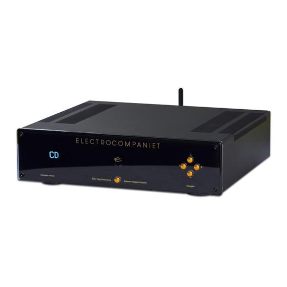
- Page 1 ECI 6 Balanced Integrated Amplifier Owner's Manual Rev.1.0 E NGL I SH...
- Page 2 Welcome to the world of Electrocompaniet! We thank you for choosing an Electrocompaniet high-end product. At Electrocompaniet we are relentlessly focused on developing audio equipment that is capable of bringing the fabulous experi- ence of the concert hall into the very heart of your home.
- Page 3 • 2 pcs. AAA/LR03 Batteries Set up procedure Before connecting the ECI 6 to the AC Power outlet, check that the main voltage indicated on the rear panel corresponds to the line voltage in the country were you intend to use the unit.
-
Page 4: Preamp Out
RCA shorting plug. HT (Home Theatre) HT is a direct input where the volume control is bypassed. ECI 6 will work like a power amplifier with fixed gain. When selected the output will be muted for a few seconds as a safety against accidental overload. -
Page 5: Trigger Input/Output
CD-player (or other equipment with 12V trigger input) when ECI 6 is powered up. When ECI 6 powers up the 12V trigger output will be set to 12V and will support up to 75 mA current output. Please keep the cur- rent draw below 75 mA by limiting the number of devices connected to the 12V trigger output. -
Page 6: Navigator Window
When the ECI 6 is not to be used for a long period of time, use the main switch to turn the unit off. Then disconnect the AC main cord for maxi- mum safety. -
Page 7: Error Codes
Error codes If the ECI 6 is not working properly, the display will show an error code. The error codes are: Display Error Description What to do text DC FAULT LEFT DC voltage left channel Please contact service center. DC FAULT... -
Page 8: Input Configurations
Replacing a blown main fuse The main fuse is located in a small drawer inside the AC inlet of the unit. If, for some reason the fuse is blown, turn the unit off, and remove the AC cord from the AC inlet. Open the drawer with a small screwdriver and remove the blown fuse. -
Page 9: Preamplifier Section
Technical specifications ECI 6: The following technical data were measured on randomized test objects and are typical data. All measurements are made at 120V / 240V // 50Hz / 60Hz. Clipping point of the amplifier is set to a level where total harmonic distortion (THD) is 0.2 %. - Page 10 ECI 6 Front panel illustration...
- Page 11 ECI 6 Rear panel illustration...
- Page 12 How to connect the system (Analog Inputs)
-
Page 13: Remote Control
When using the remote control, the TOP MENU SETUP front end of the remote control should be pointed to the front panel of your ECI 6. A free line of sight is required between the remote and the infrared sensor on the front pane... -
Page 14: Important Notice
For optimal sonic performance, the ECI 6 should be burned in for a mini- mum time of 72 hours. The easiest way to burn in your ECI 6 is to put a signal at any input, without the speakers connected In daily operation, switch off the ECI 6 by using the MUTE button on the remote control. - Page 16 Verify line voltage before use. Do not remove cover. No user serviceable parts inside. Refer servicing to qualified service personal. The warranty is void if the product is tampered with by non-authorised personnel. Use only authorized Electrocompaniet service center. Made in Norway www.electrocompaniet.no...
Need help?
Do you have a question about the ECI 6 and is the answer not in the manual?
Questions and answers