
Related Manuals for Nexcom NEX 650


Summary of Contents for Nexcom NEX 650
- Page 1 NEXCOM International Co., Ltd. Intelligent Platform & Services Business Unit Embedded Computing (Industrial Motherboard) NEX 650 User Manual NEXCOM International Co., Ltd. www.nexcom.com Published September 2017...
-
Page 2: Table Of Contents
Knowing Your NEX 650 ................4 LAN2 and USB 2.0 Ports ..............16 Top View .....................4 LAN1 and USB 3.0 Ports ..............17 Rear I/O View ..................5 Audio Connectors ................18 Copyright © 2017 NEXCOM International Co., Ltd. All Rights Reserved. NEX 650 User Manual... - Page 3 About BIOS Setup .................30 When to Configure the BIOS ..............30 Default Configuration ................31 Entering Setup ..................31 Legends ....................31 BIOS Setup Utility ..................33 Main ....................33 Advanced ..................34 Copyright © 2017 NEXCOM International Co., Ltd. All Rights Reserved. NEX 650 User Manual...
-
Page 4: Preface
Acknowledgements The product(s) described in this manual complies with all applicable NEX 650 is a trademark of NEXCOM International Co., Ltd. All other product European Union (CE) directives if it has a CE marking. For computer systems names mentioned herein are registered trademarks of their respective to remain CE compliant, only CE-compliant parts may be used. -
Page 5: Rohs Compliance
0.1% or 1,000ppm, and Polybrominated diphenyl Ethers (PBDE) < 0.1% or 1,000ppm. In order to meet the RoHS compliant directives, NEXCOM has established an engineering and manufacturing task force in to implement the introduction of green products. The task force will ensure that we follow the standard... -
Page 6: Warranty And Rma
(manuals, cable, etc.) and any components from the card, such as CPU and RAM. If the components were suspected as part of the problems, ▪ If RMA goods can not be repaired, NEXCOM will return it to the customer please note clearly which components are included. Otherwise, NEXCOM without any charge. - Page 7 ESD workstation. If no such station is available, you can provide some ESD protection by wearing an antistatic wrist strap and attaching it to a metal part of the computer chassis. Copyright © 2017 NEXCOM International Co., Ltd. All Rights Reserved. NEX 650 User Manual...
-
Page 8: Safety Information
There is a danger of explosion if battery is incorrectly replaced. Replace only with the same or equivalent type recommended by the manufacturer. Discard used batteries according to the manufacturer’s instructions. viii Copyright © 2017 NEXCOM International Co., Ltd. All Rights Reserved. NEX 650 User Manual... -
Page 9: Safety Precautions
RECOMMENDED BY THE MANUFACTURER. DISCARD USED BATTERIES ACCORDING TO THE MANUFACTURER’S INSTRUCTIONS. 10. All cautions and warnings on the equipment should be noted. Copyright © 2017 NEXCOM International Co., Ltd. All Rights Reserved. NEX 650 User Manual... -
Page 10: Technical Support And Assistance
Preface Technical Support and Assistance Conventions Used in this Manual 1. For the most updated information of NEXCOM products, visit NEXCOM’s Warning: website at www.nexcom.com. Information about certain situations, which if not observed, can cause personal injury. This will prevent injury to yourself 2. -
Page 11: Global Service Contact Information
13F, No.920, Chung-Cheng Rd., ZhongHe District, Beijing, 100094, China New Taipei City, 23586, Taiwan, R.O.C. Tel: +86-10-5704-2680 Tel: +886-2-8226-7796 Fax: +86-10-5704-2681 Fax: +886-2-8226-7792 Email: sales@nexcom.cn Email: sales@nexcom.com.tw www.nexcom.cn www.nexcom.com.tw Copyright © 2017 NEXCOM International Co., Ltd. All Rights Reserved. NEX 650 User Manual... - Page 12 Hui Yin Ming Zun Building Room 1108, Building No. 11, 599 Yunling Road, Putuo District, Shanghai, 200062, China Tel: +86-21-6125-8282 Fax: +86-21-6125-8281 Email: frankyang@nexcom.cn www.nexcom.cn Copyright © 2017 NEXCOM International Co., Ltd. All Rights Reserved. NEX 650 User Manual...
-
Page 13: Package Contents
Preface Package Contents Before continuing, verify that the NEX 650 package that you received is complete. Your package should have all the items listed in the following table. Item Name NEXCOM NEX 650 Motherboard NEXCOM NEX 650 Driver CD NEXCOM NEX 650 Quick Guide... -
Page 14: Ordering Information
Preface Ordering Information The following information below provides ordering information for NEX 650. NEX 650 (P/N: 10G00065001X1) Mini-ITX form factor powered by onboard 4-core Intel Celeron J1900 ® ® processor that integrates with 24/48-bit LVDS & up to 8GB DDR3/L memory &... -
Page 15: Chapter 1: Product Introduction
▪ 1 x Dual channel 24-bit LVDS; 4 x USB 3.0, 6 x USB 2.0, 2 x SATA2; Gigabit LAN: 2 x Realtek LAN ▪ 12~24 V DC-in power support Copyright © 2017 NEXCOM International Co., Ltd. All Rights Reserved. NEX 650 User Manual... -
Page 16: Hardware Specifications
▪ LVDS: dual channel 24-bit, max resolution 1920 x 1200 @ 60Hz ▪ SATA PWR output con: 1 ▪ HDMI: supports HDMI 1.3a, max resolution 1920 x 1200 ▪ Speaker header: 1 Copyright © 2017 NEXCOM International Co., Ltd. All Rights Reserved. NEX 650 User Manual... - Page 17 ▪ Power on: AT/ATX supported ▪ AT: directly PWR on as power input ready ▪ ATX: press button to PWR on after power input ready Environment ▪ Temperature: 0ºC~60ºC Copyright © 2017 NEXCOM International Co., Ltd. All Rights Reserved. NEX 650 User Manual...
-
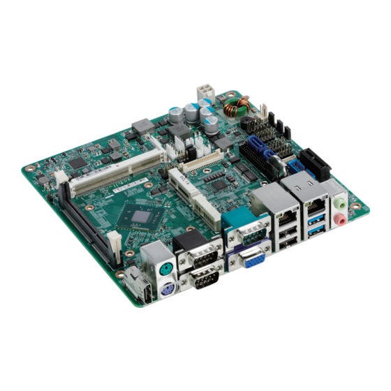
Page 18: Knowing Your Nex 650
Front Panel Audio 4-pin ATX Power 2W Audio APM Output System Panel Header USB 2.0 PCIe COM4/ Backlight DI/DO System Fan DI/DO COM6 Control Level Power Select JGPIO_JP Copyright © 2017 NEXCOM International Co., Ltd. All Rights Reserved. NEX 650 User Manual... -
Page 19: Rear I/O View
Chapter 1: Product Introduction Rear I/O View PS/2 Mouse COM1 COM3 LAN2 LAN1 Line-out HDMI PS/2 Keyboard COM2 USB 2.0 USB 3.0 Mic-in Copyright © 2017 NEXCOM International Co., Ltd. All Rights Reserved. NEX 650 User Manual... -
Page 20: Chapter 2: Jumpers And Connectors
Static electricity can damage many of the electronic ▪ Use correct screws and do not over tighten screws. components. Humid environments tend to have less static electricity than Copyright © 2017 NEXCOM International Co., Ltd. All Rights Reserved. NEX 650 User Manual... -
Page 21: Jumper Settings
(on) and open (off). Two-Pin Jumpers: Open (Left) and Short (Right) Three-Pin Jumpers: Pins 1 and 2 are Short Copyright © 2017 NEXCOM International Co., Ltd. All Rights Reserved. NEX 650 User Manual... -
Page 22: Locations Of The Jumpers And Connectors
LVDS1 USB2 PANEL1 BLT_PWM1 LPT1 SATA1 MPCIE1 COM6 COM4 SATA2 MPCIE1 TPM1 MSATA1 USB3 SPEAKER1 PWR_COM2 HDMI1 MSATA_SEL1 PWR_COM1 HD_AUDIO1 AUDIO1 AUDIO2 COM1 VGA1 LAN2 LAN1 Copyright © 2017 NEXCOM International Co., Ltd. All Rights Reserved. NEX 650 User Manual... -
Page 23: Jumpers
1-2 On Short AT Mode 1-2 On Short +3V Level 2-3 On Short ATX Mode 2-3 On Short +5V Level 1-2 On: default 1-2 On: default Copyright © 2017 NEXCOM International Co., Ltd. All Rights Reserved. NEX 650 User Manual... -
Page 24: Panel Power Selection (Lcd_Vcc)
2-3 On Short LVDD: +5V 2-3 On Short LCD_BLT_VCC: +12V 4-5 On Short LVDD: +12V 4-5 On Short LCD_BLT_VCC: DC_IN 1-2 On: default 1-2 On: default Copyright © 2017 NEXCOM International Co., Ltd. All Rights Reserved. NEX 650 User Manual... -
Page 25: Com1 Power Select
1-2 On Short 3-4 On Short +12V 3-4 On Short +12V 5-6 On Short +5VSB 5-6 On Short 7-8 On Short 5-6 On: default 7-8 On: default Copyright © 2017 NEXCOM International Co., Ltd. All Rights Reserved. NEX 650 User Manual... -
Page 26: Msata Select
Connector location: CLRCMOS1 Status Settings Status Settings 1-2 On Short For mSATA1 Short Normal 1-2 Off Open For SATA2 Short Clear CMOS 1-2 Off: default 1-2 On: default Copyright © 2017 NEXCOM International Co., Ltd. All Rights Reserved. NEX 650 User Manual... -
Page 27: Digital Input/Output Power Select
Connector type: 1x3 3-pin header Connector location: JGPIO_PWR1 Connector location: JGPIO_JP1 Status Settings Status Settings 1-2 On Short +12V 1-2 On Short High 2-3 On Short 2-3 On Short Copyright © 2017 NEXCOM International Co., Ltd. All Rights Reserved. NEX 650 User Manual... -
Page 28: Connector Pin Definitions
Connector location: KM1 Mouse Keyboard Definition Definition Definition Definition HDMI_DATA2_P_C KDAT_C HDMI_DATA2_N_C HDMI_DATA1_P_C +5V_PS2 HDMI_DATA1_N_C KCLK_C HDMI_DATA0_P_C MDAT_C HDMI_DATA0_N_C HDMI_CLK_P_C +5V_PS2 HDMI_CLK_N_C MCLK_C HDMI_CTRL_CLK_C HDMI_CTRL_DATA_C +5V_HDMI HDMI_HPD_C Copyright © 2017 NEXCOM International Co., Ltd. All Rights Reserved. NEX 650 User Manual... -
Page 29: Com1 Port
Connector location: COM1 Connector location: VGA1 RS232 RS422 RS485 Definition Definition VGA_R VGA_G Definition Definition Definition VGA_B DCD# RTX- RTX+ DTR# VGA_DDC_DATA G_HSYNC G_VSYNC DSR# VGA_DDC_CLK RTS# CTS# Copyright © 2017 NEXCOM International Co., Ltd. All Rights Reserved. NEX 650 User Manual... -
Page 30: Lan2 And Usb 2.0 Ports
10Mbps or no link Definition Definition Definition Definition +5V_H_USB2_P12 S_USB_C_DN1 LAN1_VCT MDI0P_LAN1 S_USB_C_DP1 MDI0N_LAN1 MDI1P_LAN1 +5V_H_USB2_P12 S_USB_C_DN2 MDI1N_LAN1 MDI2P_LAN1 S_USB_C_DP2 MDI2N_LAN1 MDI3P_LAN1 MDI3N_LAN1 LAN1_ACT_P LAN1_LED_ACT# LAN1_LINK100# LAN1_1000_P Copyright © 2017 NEXCOM International Co., Ltd. All Rights Reserved. NEX 650 User Manual... -
Page 31: Lan1 And Usb 3.0 Ports
USB2_C_N1 LAN0_VCT MDI0P_LAN0 USB2_C_P1 MDI0N_LAN0 MDI1P_LAN0 USB3_RX_C_N1 USB3_RX_C_P1 MDI1N_LAN0 MDI2P_LAN0 USB3_TX_C_N1 MDI2N_LAN0 MDI3P_LAN0 USB3_TX_C_P1 +5V_USB3_P12 MDI3N_LAN0 USB2_C_N2 USB2_C_P2 LAN0_ACT_P LAN0_LED_ACT# USB3_RX_C_N2 LAN0_LINK100# LAN0_1000_P USB3_RX_C_P2 USB3_TX_C_N2 USB3_TX_C_P2 Copyright © 2017 NEXCOM International Co., Ltd. All Rights Reserved. NEX 650 User Manual... -
Page 32: Audio Connectors
Chapter 2: Jumpers and Connectors Audio Connectors Connector type: 2x 3.5mm jack Connector location: AUDIO1 and AUDIO2 Line-out Mic-in Definition Definition MIC_OUT_L_C MIC1_JD AGND_P MIC_OUT_R_C LINE_OUT_L_C LINEOUT1_JD AGND_G LINE_OUT_R_C Copyright © 2017 NEXCOM International Co., Ltd. All Rights Reserved. NEX 650 User Manual... -
Page 33: Internal Connectors
Connector type: 2x5 10-pin header Connector location: SATA1 and SATA2 Connector location: USB1 and USB2 Definition Definition Definition Definition TXP0 USB_PWR USB_PWR TXN0 RXN0 RXP0 DUMMY Copyright © 2017 NEXCOM International Co., Ltd. All Rights Reserved. NEX 650 User Manual... -
Page 34: System Panel Header
Connector type: 2x5 10-pin header Connector type: 1x4 4-pin header Connector location: PANEL1 Connector location: SPEAKER1 Definition Definition Definition HDLED+ PLED+ OUTLN HDLED- PLED- OUTLP PWRBTN# OUTRP RESET# OUTRN Copyright © 2017 NEXCOM International Co., Ltd. All Rights Reserved. NEX 650 User Manual... -
Page 35: Front Panel Audio Header
Connector type: 2x5 10-pin header Connector type: 1x4 4-pin Wafer Connector location: HD_AUDIO1 Connector location: CPUF1 Definition Definition Definition MIC2_L MIC2_R PRESENCE# +12V OUT2_R MIC_RET CPU_FAN_SPEED J_SENSE FAN_SPEED_CONTROL OUT2_L OUT_RET Copyright © 2017 NEXCOM International Co., Ltd. All Rights Reserved. NEX 650 User Manual... -
Page 36: Dc-In Power Connector
Connector location: LPT1 Definition Definition Definition STB# AFD# SPD0 ERROR# DC Input SPD1 PINIT# DC Input SPD2 SLIN# SPD3 SPD4 SPD5 SPD6 SPD7 ACK# BUSY SLCT Copyright © 2017 NEXCOM International Co., Ltd. All Rights Reserved. NEX 650 User Manual... -
Page 37: Lvds Connector
SIO_GP23 LVDS_A_DATA1# LVDS_A_DATA1 JGPIO_PWR LVDS_A_DATA2# LVDS_A_DATA2 LVDS_A_DATA3# LVDS_A_DATA3 LVDS_A_CLK# LVDS_A_CLK LVDS_B_DATA0# LVDS_B_DATA0 LVDS_B_DATA1# LVDS_B_DATA1 LVDS_B_DATA2# LVDS_B_DATA2 DPLVDD_EN LVDS_B_DATA3# LVDS_B_DATA3 LVDS_B_CLK# LVDS_B_CLK CON_LBKLT_EN CON_LBKLT_CTL LCD_BLT_VCC LCD_BLT_VCC LCD_BLT_VCC Copyright © 2017 NEXCOM International Co., Ltd. All Rights Reserved. NEX 650 User Manual... -
Page 38: Backlight Volume Control
Connector type: 1x6 6-pin header Connector location: BLT_VOL1 Connector location: BLT_PWR1 Definition Definition Definition Definition GPIO_VOL_UP GPIO_VOL_DW PWRDN LVDS1 BLUP BL CTL BL EN LVDS1 BLDW LCD_BLT_VCC LCD_BLT_VCC Copyright © 2017 NEXCOM International Co., Ltd. All Rights Reserved. NEX 650 User Manual... -
Page 39: Sata Power Output Connector
Chassis Intrusion Pin Headers Connector type: 1x4 4-pin Wafer Connector type: 1x2 2-pin header Connector location: SATA_PWR1 Connector location: CI1 and CI2 Definition Definition +12V Signal Copyright © 2017 NEXCOM International Co., Ltd. All Rights Reserved. NEX 650 User Manual... -
Page 40: Com4 And Com6 Pin Headers
PORT B USB CM_P9 PORT B USB Vbus PORT A USB PORT A USB PORT A USB PORT A USB PORT A USB PORT A USB Vbus Copyright © 2017 NEXCOM International Co., Ltd. All Rights Reserved. NEX 650 User Manual... -
Page 41: Tpm Connector
Connector type: 1x10 10-pin header Connector type: 1x3 3-pin Wafer Connector location: TPM1 Connector location: SYSF1 Definition Definition Definition PLTRST_3P3# S_ILB_LPC_CLK_1 S_ILB_LPC_FRAME# +12V S_ILB_LPC_AD_3 S_ILB_LPC_AD_2 FAN_SPEED S_ILB_LPC_AD_1 S_ILB_LPC_AD_0 ILB_LPC_SERIRQ +3.3V Copyright © 2017 NEXCOM International Co., Ltd. All Rights Reserved. NEX 650 User Manual... -
Page 42: Mini-Pcie/Msata Connector
+3.3VSB_4 GND8 GND5 UIM_VPP +3.3VSB_5 LED_WWAN# REV10/UIM_C8 GND11 GND14 LED_WLAN# REV9/UIM_C4 W_DISABLE# REV4 LED_WPAN# GND4 PERST# REV3 1.5V_1 PERn0 +3.3VSB_1 REV2 GND7 PERp0 GND10 REV1 3.3VSB_2 Copyright © 2017 NEXCOM International Co., Ltd. All Rights Reserved. NEX 650 User Manual... -
Page 43: Block Diagram
R8111G RJ45 HUB PORT: 1 2X5 2.54mm PIN HEADER HUB PORT: 0 PCIE SLOT PCI-E*1 BUS PORT: 1 2X5 2.54mm PCI-E*1 BUS PORT: 2 MINI PCIE Copyright © 2017 NEXCOM International Co., Ltd. All Rights Reserved. NEX 650 User Manual... -
Page 44: Chapter 3: Bios Setup
This chapter describes how to use the BIOS setup program for NEX 650. The The settings made in the setup program affect how the computer performs. BIOS screens provided in this chapter are for reference only and may change It is important, therefore, first to try to understand all the setup options, and if the BIOS is updated in the future. -
Page 45: Default Configuration
Powering on the computer and immediately pressing <Del> allows you to enter Setup. Load optimized default values. Press the key to enter Setup: Saves and exits the Setup program. Press <Enter> to enter the highlighted sub-menu Copyright © 2017 NEXCOM International Co., Ltd. All Rights Reserved. NEX 650 User Manual... - Page 46 When “” appears on the left of a particular field, it indicates that a submenu which contains additional options are available for that field. To display the submenu, move the highlight to that field and press Copyright © 2017 NEXCOM International Co., Ltd. All Rights Reserved. NEX 650 User Manual...
-
Page 47: Bios Setup Utility
+/-: Change Opt. F1: General Help F2: Previous Values F3: Optimized Defaults F4: Save & Exit ESC: Exit Version 2.17.1249. Copyright (C) 2017 American Megatrends, Inc. Copyright © 2017 NEXCOM International Co., Ltd. All Rights Reserved. NEX 650 User Manual... -
Page 48: Advanced
The options are Suspend Disabled and S3 (Suspend to Version 2.17.1249. Copyright (C) 2017 American Megatrends, Inc. RAM). OS Selection Configures the target OS. The options are Windows 7 and Windows 8.X. Copyright © 2017 NEXCOM International Co., Ltd. All Rights Reserved. NEX 650 User Manual... -
Page 49: Nct6106D Super Io Configuration
Enables or disables the serial port. Displays the Super I/O chip used on the board. Serial Port Mode Select this to change the serial port mode to RS232, RS422 or RS485. Copyright © 2017 NEXCOM International Co., Ltd. All Rights Reserved. NEX 650 User Manual... -
Page 50: Serial Port 2 Configuration
Select this to change the serial port mode to RS232, RS422 or RS485. Select this to change the serial port mode to RS232, RS422 or RS485. Copyright © 2017 NEXCOM International Co., Ltd. All Rights Reserved. NEX 650 User Manual... -
Page 51: Serial Port 4 Configuration
Version 2.17.1249. Copyright (C) 2017 American Megatrends, Inc. Version 2.17.1249. Copyright (C) 2017 American Megatrends, Inc. Serial Port Serial Port Enables or disables the serial port. Enables or disables the serial port. Copyright © 2017 NEXCOM International Co., Ltd. All Rights Reserved. NEX 650 User Manual... -
Page 52: Parallel Port Configuration
Parallel Port Enables or disables the parallel port. Change Settings Selects the optimal setting for the Super IO device. Device Mode Selects the parallel port mode. Copyright © 2017 NEXCOM International Co., Ltd. All Rights Reserved. NEX 650 User Manual... - Page 53 Detects and displays the current system temperature. CPU Temperature Detects and displays the current CPU temperature. SYS Fan Speed Detects and displays the current system fan speed. Copyright © 2017 NEXCOM International Co., Ltd. All Rights Reserved. NEX 650 User Manual...
-
Page 54: Cpu Configuration
3 or lesser than 3. F4: Save & Exit ESC: Exit Version 2.17.1249. Copyright (C) 2017 American Megatrends, Inc. Copyright © 2017 NEXCOM International Co., Ltd. All Rights Reserved. NEX 650 User Manual... -
Page 55: Ppm Configuration
Enables or disables SATA port 0 and SATA port 1. SATA Port0 Hotplug and SATA Port1 Hotplug Enables or disables hotplug support on SATA port 0 and SATA port 1. Copyright © 2017 NEXCOM International Co., Ltd. All Rights Reserved. NEX 650 User Manual... - Page 56 This option configures the Serial ATA drives to use AHCI (Advanced Host Controller Interface). AHCI allows the storage driver to enable the advanced Serial ATA features which will increase storage performance. Copyright © 2017 NEXCOM International Co., Ltd. All Rights Reserved. NEX 650 User Manual...
-
Page 57: Chipset
This is a workaround for OSs that does not support XHCI hand-off and EHCI Configures the LVDS display resolution. hand-off. The XHCI and EHCI ownership change should be claimed by the XHCI and EHCI driver respectively. Copyright © 2017 NEXCOM International Co., Ltd. All Rights Reserved. NEX 650 User Manual... -
Page 58: South Bridge
Control detection of the Azalia device. Disabled Azalia will be unconditionally disabled. Enabled Azalia will be unconditionally enabled. Azalia HDMI Codec Enables or disables internal HDMI codec for Azalia. Copyright © 2017 NEXCOM International Co., Ltd. All Rights Reserved. NEX 650 User Manual... -
Page 59: Pci Express Configuration
Enables or disables the PCI Express ports 0 to 3 on the chipset. EHCI controller must always be enabled. USB EHCI Debug Enables or disables PCH EHCI debug capability. Copyright © 2017 NEXCOM International Co., Ltd. All Rights Reserved. NEX 650 User Manual... -
Page 60: Security
Adjust the boot sequence of the system. Boot Option #1 is the first boot device that the system will boot from, next will be #2 and so forth. Copyright © 2017 NEXCOM International Co., Ltd. All Rights Reserved. NEX 650 User Manual... -
Page 61: Save & Exit
<Enter>. You may be prompted to confirm again before exiting. Restore Defaults To restore the BIOS to default settings, select this field then press <Enter>. A dialog box will appear. Confirm by selecting Yes. Copyright © 2017 NEXCOM International Co., Ltd. All Rights Reserved. NEX 650 User Manual... -
Page 62: Appendix A: Power Consumption
USB 2.0 Hub (GL850G) 0.18 0.18 PS/2 KB & MS 0.55 Total Current 7.74 1.63 0.41 0.065 15.53 7.723 Total Watt 92.88 5.379 0.41 0.117 77.65 25.4859 1.785 Copyright © 2017 NEXCOM International Co., Ltd. All Rights Reserved. NEX 650 User Manual... - Page 63 SIO(NCT6106D) GPIO USB 3.0 Hub (ASM1074) USB 2.0 Hub (GL850G) PS/2 KB & MS Total Current 1.136 0.27 Total Watt 7.29 0.54 1.704 0.486 0.81 245.6369 Copyright © 2017 NEXCOM International Co., Ltd. All Rights Reserved. NEX 650 User Manual...
Need help?
Do you have a question about the NEX 650 and is the answer not in the manual?
Questions and answers