
Subscribe to Our Youtube Channel
Related Manuals for Nexcom NEX 605


Summary of Contents for Nexcom NEX 605
- Page 1 NEXCOM International Co., Ltd. Industrial Computing Solutions Embedded Computing (Industrial Motherboard) NEX 605 User Manual NEXCOM International Co., Ltd. www.nexcom.com Published July 2012...
-
Page 2: Table Of Contents
Knowing Your NEX 605 ..............5 SGPIO (SFF-8485) connector........17 Chapter 2: Jumpers and Connectors ..........6 Before You Begin ................6 USB6/7 Connector ............ 17 Copyright © 2012 NEXCOM International Co., Ltd. All rights reserved NEX 605 User Manual... - Page 3 When to Configure the BIOS ............29 Default Configuration..............30 Entering Setup................30 Legends..................30 BIOS Setup Utility ................32 Main ..................32 Advanced ................33 Chipset ................41 Copyright © 2012 NEXCOM International Co., Ltd. All rights reserved NEX 605 User Manual...
-
Page 4: Preface
The product(s) described in this manual complies with all applicable European Union (CE) directives if it has a CE marking. For computer NEX 605 is a trademark of NEXCOM International Co., Ltd. All other systems to remain CE compliant, only CE-compliant parts may be used. -
Page 5: Rohs Compliance
0.1% or 1,000ppm, and Polybrominated diphenyl Ethers (PBDE) < 0.1% or 1,000ppm. In order to meet the RoHS compliant directives, NEXCOM has established an engineering and manufacturing task force in to implement the introduction of green products. The task force will ensure that we follow... -
Page 6: Warranty And Rma
• Replace with 3rd party products if needed. and describe the problems on the “NEXCOM RMA Service Form” for the • If RMA goods can not be repaired, NEXCOM will return it to the cus- RMA number apply process. tomer without any charge. -
Page 7: Safety Information
Warranty and RMA • If RMA goods can not be repaired, NEXCOM will return it to the • Avoid using the system near water, in direct sunlight, or near a heating customer without any charge device. • The load of the system unit does not solely rely for support from the Warnings rackmounts located on the sides. -
Page 8: Safety Precautions
The equipment does not work well, or you cannot get it to work the equipment to the power outlet. according to the user’s manual. viii Copyright © 2012 NEXCOM International Co., Ltd. All rights reserved NEX 605 User Manual... -
Page 9: Technical Support And Assistance
Conventions Used in this Manual Technical Support and Assistance Warning: Information about certain situations, which if not 1. For the most updated information of NEXCOM products, visit observed, can cause personal injury. This will prevent injury NEXCOM’s website at www.nexcom.com. -
Page 10: Global Service Contact Information
No. 450 Caoyang Rd., Shanghai, 200062, China Tel: +1-510-656-2248 Tel: +39 02 9628 0333 Tel: +86-21-6150-8008 Fax: +1-510-656-2158 Fax: +39 02 9619 8846 Fax: +86-21-3251-6358 http://www.nexcom.com www.nexcomitalia.it http://www.nexcom.cn Copyright © 2012 NEXCOM International Co., Ltd. All rights reserved NEX 605 User Manual... - Page 11 Fax: +86-27-8722-7400 Tel: +81-3-5419-7830 http://www.nexcom.cn Fax: +81-3-5419-7832 http://www.nexcom-jp.com China-Chengdu Office 9F, Shuxiangxie,Xuefu Garden, No.12 Section 1, South Yihuan Rd., Chengdu, 610061,China Tel: +86-28-8523-0186 Fax: +86-28-8523-0186 http://www.nexcom.cn Copyright © 2012 NEXCOM International Co., Ltd. All rights reserved NEX 605 User Manual...
-
Page 12: Package Contents
Package Contents Package Contents Item Name 5044440079X00 GASKET FOR VIA CPU KGS:C-4505(20X20x1)+G4000 5044440090X00 (H)THERMAL PAD APUS:3A2015001001500 5050300517X00 CPU HEATSINK FOR NEX605 SHYUNG SHUHN Copyright © 2012 NEXCOM International Co., Ltd. All rights reserved NEX 605 User Manual... -
Page 13: Ordering Information
Ordering Information Ordering Information The following information below provides ordering information for NEX 605. NEX 605-2550 (P/N: 10G00060500X0) RoHS Compliant Mini ITX, Intel ® Atom™ D2550 processor and based on Intel ® integrated graphics engine w/ VGA/18-bit LVDS/HDMI /8x USB2.0/4x COMs/... -
Page 14: Chapter 1: Product Introduction
• Audio Mic-in/ Line-out, (internal Line-in) • 1x Mini-PCIe (1x full-size/ SIM tray), 1x PCIe x4 • Standard ATX v.2.0 input by AT/ ATX power mode Copyright © 2012 NEXCOM International Co., Ltd. All rights reserved NEX 605 User Manual... -
Page 15: Hardware Specifications
• 2x RJ45 with LEDs build-in 2x dual stackable USB type A connectors on • 1x Mini-PCIe (1x full-size/ SIM tray) edge I/O • 1x PCIE X4 slot Copyright © 2012 NEXCOM International Co., Ltd. All rights reserved NEX 605 User Manual... - Page 16 • Power requirement: ATX Input, jumper AT/ ATX (default) mode Watchdog Timer • Onboard 2x 12-pins standard ATX version 2.0 power connector • Watchdog timeout can be programmed by software from 1 second to Copyright © 2012 NEXCOM International Co., Ltd. All rights reserved NEX 605 User Manual...
- Page 17 • Operating temperatures: 0°C to 60°C • Storage temperature: -20°C to 85°C • Relative humidity: Operating 10% to 90%, non-condensing Certifications • CE approval • FCC Class A Copyright © 2012 NEXCOM International Co., Ltd. All rights reserved NEX 605 User Manual...
-
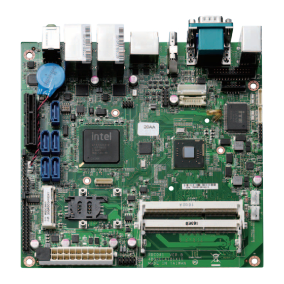
Page 18: Knowing Your Nex 605
RTC Battery SM BUS SATA5 FP Control ATX/AT Select FAN Connector Mini-PCIe FAN Connector SATA & LAN LED ATX Power Connector SIM Card Connector USB6/7 DIMM1 DIMM2 Copyright © 2012 NEXCOM International Co., Ltd. All rights reserved NEX 605 User Manual... -
Page 19: Chapter 2: Jumpers And Connectors
Static electricity can damage many of the • Use correct screws and do not over tighten screws. electronic components. Humid environments tend to have less static Copyright © 2012 NEXCOM International Co., Ltd. All rights reserved NEX 605 User Manual... -
Page 20: Jumper Settings
(on) and open (off). Two-Pin Jumpers: Open (Left) and Short (Right) Three-Pin Jumpers: Pins 1 and 2 Are Short Copyright © 2012 NEXCOM International Co., Ltd. All rights reserved NEX 605 User Manual... -
Page 21: Locations Of The Jumpers And Connectors
Locations of the Jumpers and Connectors JFP1 The figure below shows the location of the jumpers and connectors. CN10 CN17 CON1 CON2 CN11 CN12 CN14 CN13 CN15 CN16 Copyright © 2012 NEXCOM International Co., Ltd. All rights reserved NEX 605 User Manual... -
Page 22: Jumpers
Connector type: 1x3 3-pin header Connector location: JP1 Connector location: JP3 Settings Settings 1-2 On Normal 1-2 On 2-3 On Clear BIOS 2-3 On 1-2 On: default 2-3 On: default Copyright © 2012 NEXCOM International Co., Ltd. All rights reserved NEX 605 User Manual... -
Page 23: Lvds Backlight Power Select
Chapter 2: Jumpers and Connectors LVDS Backlight Power Select Connector type: 1x3 3-pin header Connector location: JP7 Settings 3.3V 1-2 On: default Definition VCC3 VCC_SEL VCC5 Copyright © 2012 NEXCOM International Co., Ltd. All rights reserved NEX 605 User Manual... -
Page 24: Connector Pin Definitions
Connector location: CN13 Connector location: CN16 Definition Definition Definition Definition KB DATA GREEN 5VDUAL BLUE KB CLOCK MS DATA 5VDUAL MS CLOCK DDC DATA HSYNC VSYNC DDC CLOCK Copyright © 2012 NEXCOM International Co., Ltd. All rights reserved NEX 605 User Manual... -
Page 25: Hdmi
Connector location: CON2 Definition Definition Definition Definition Data2+ Data2– Data1+ SATA1_TXP SATA0_TXP Data1– SATA1_TXN SATA0_TXN Data0+ Data0– Clock+ SATA1_RXN SATA0_RXN Clock- SATA1_RXP SATA0_RXP HDMI SCL HDMI SDA Copyright © 2012 NEXCOM International Co., Ltd. All rights reserved NEX 605 User Manual... -
Page 26: Lan1 And Usb0/1 Ports
LAN1_MDI0P LAN2_MDI0P LAN1_MDI0N LAN1_MDI1P LAN2_MDI0N LAN2_MDI1P LAN1_MDI1N LAN1_MDI2P LAN2_MDI1N LAN2_MDI2P LAN1_MDI2N LAN1_MDI3P LAN2_MDI2N LAN2_MDI3P LAN1_MDI3N LAN2_MDI3N LAN1_100M# LAN1_1G# LAN2_100M# LAN2_1G# LAN1_ACTLED# LAN1_ACTLED# POWER LAN2_ACTLED# LAN2_ACTLED# POWER Copyright © 2012 NEXCOM International Co., Ltd. All rights reserved NEX 605 User Manual... -
Page 27: Audio Connectors
Chapter 2: Jumpers and Connectors Audio Connectors Connector type: 2x 3.5mm TRS Connector location: CN2 Definition Definition MIC1_L MIC1_JD MIC1_R FRONT_L FRONT_JD FRONT_R Copyright © 2012 NEXCOM International Co., Ltd. All rights reserved NEX 605 User Manual... -
Page 28: Internal Connectors
PWR_LED_P SATA0_P_LED SATA0_S_LED SATA_LED_N SATA1_P_LED SATA1_S_LED PWRBT_N SATA2_P_LED SATA2_S_LED RST_BTN_N SATA3_P_LED SATA3_S_LED SATA4_P_LED SATA4_S_LED SATA5_P_LED SATA5_S_LED SYS_P_LED SYS_S_LED +3.3V SATALED_N 3VSB LAN1_ACT_N 3VSB LAN2_ACT_N PWRBTN+ PWRBTN+ Copyright © 2012 NEXCOM International Co., Ltd. All rights reserved NEX 605 User Manual... -
Page 29: Smbus Connector
Line-in Connector Connector type: 1x4 4-pin header Connector type: 1x4 4-pin header Connector location: JP2 Connector location: J8 Definition Definition 3VSB LINEIN_R SMB_DATA LINEIN_JD SMB_CLK LINEIN_L Copyright © 2012 NEXCOM International Co., Ltd. All rights reserved NEX 605 User Manual... -
Page 30: Sgpio (Sff-8485) Connector
Connector type: 2x5 10-pin header Connector location: JP6 Connector location: J2 Definition Definition Definition Definition SCLOCK SDATAOUT0 5VDUAL 5VDUAL SLOAD SDATAOUT1 DATA6_N DATA7_N +3.3V DATA6_P DATA7_P Copyright © 2012 NEXCOM International Co., Ltd. All rights reserved NEX 605 User Manual... -
Page 31: Usb8/9 Connector
Connector type: 1x7 JST, 7-pin header Connector location: J3 Connector location: J4 Definition Definition Definition Definition 5VDUAL 5VDUAL Backlight power(+12V) DATA8_N DATA9_N Backlight power(+12V) Backlight brightness control DATA8_P DATA9_P Backlight enable Copyright © 2012 NEXCOM International Co., Ltd. All rights reserved NEX 605 User Manual... -
Page 32: Com2 Connector (Rs232)
Connector type: 1x10 10-pin header Connector location: CN15 Connector location: J10 Definition Definition DCD2 RXD2 TXD2 DTR2 DSR2 RTS2 CTS2 Definition Definition DCD3 RXD3 TXD3 DTR3 DSR3 RTS3 CTS3 Copyright © 2012 NEXCOM International Co., Ltd. All rights reserved NEX 605 User Manual... -
Page 33: Com4 Connector (Rs232)
Connector type: 1x10 10-pin header Connector type: 1x5 5-pin header Connector location: J9 Connector location: JP8 Definition IRRX IRTX Definition Definition DCD4 RXD4 TXD4 DTR4 DSR4 RTS4 CTS4 Copyright © 2012 NEXCOM International Co., Ltd. All rights reserved NEX 605 User Manual... -
Page 34: Fan Connectors
Connector type: 1x4 4-pin Wafer Connector type: 1x2 JST, 2-pin header Connector location: J5 and J6 Connector location: J7 Definition Definition +12V RTC battery IN FAN_TAC FAN_CTL Copyright © 2012 NEXCOM International Co., Ltd. All rights reserved NEX 605 User Manual... -
Page 35: Atx Power Connector
Connector location: CN17 (SATA1), CN7 (SATA2), CN9 (SATA3), CN10 (SATA4), CN8 (SATA5) Definition Definition Definition +3.3V +3.3V SATA_TX_P SATA_TX_N POWEROK +5VSB +12V SATA_RX_P +12V +3.3V SATA_RX_N +3.3V PS-ON Copyright © 2012 NEXCOM International Co., Ltd. All rights reserved NEX 605 User Manual... -
Page 36: Lvds Connector
Definition VCC_LCD TX0+ TX3+ TX0-- TX3- VCC_LCD TX1+ TXCLK+ TX1- TXCLK- GND+ Definition Definition Backlight power(+12V) Power voltage RESET TX2+ Backlight power(+12V) TX2- Program voltage DATA Copyright © 2012 NEXCOM International Co., Ltd. All rights reserved NEX 605 User Manual... -
Page 37: Pio Connector
Pull high 100k to 3VSB ACK# BUSY REFCLK- SLCT AFD# REFCLK+ ERR# INIT# SLIN# Pull high 100k to 3VSB PERST# PE_RX- 3VSB PE_RX+ 1.5VSB PE_TX- PE_TX+ USB- Copyright © 2012 NEXCOM International Co., Ltd. All rights reserved NEX 605 User Manual... - Page 38 Chapter 2: Jumpers and Connectors USB+ 3VSB 3VSB 1.5VSB 3VSB Copyright © 2012 NEXCOM International Co., Ltd. All rights reserved NEX 605 User Manual...
-
Page 39: Pcie X4
PE_TX3_P +12V +12V PE_TX3_N PE_RX3_P PE_RX3_N PE_TX4_P PE_TX4_N +3.3V PE_RX4_P +3.3V PE_RX4_N +3.3V 3VSB PRSNT3# PERST# WAKE# PE_CLK_P PE_CLK_N PE_TX1_P PE_TX1_N PE_RX1_P PE_RX1_N PRSNT2# PE_TX2_P PE_TX2_N Copyright © 2012 NEXCOM International Co., Ltd. All rights reserved NEX 605 User Manual... -
Page 40: Block Diagram
INTEL: 82574L SATA 4 SATA 1 eSATA 1 SATA 5 COM1-4 MIC-IN SATA SUPPER I/O HD AUDIO LED BLOCK IT8783F/AX-L KB/MS ALC886-GR LINE-OUT LINE-IN H/W MONITOR Copyright © 2012 NEXCOM International Co., Ltd. All rights reserved NEX 605 User Manual... -
Page 41: Board Dimensions
Chapter 2: Jumpers and Connectors Board Dimensions 0.00 33.02 81.86 165.09 170.00 0.00 6.35 9.83 37.83 63.33 83.29 107.06 129.39 147.86 163.83 163.82 170.00 53.70 104.69 Copyright © 2012 NEXCOM International Co., Ltd. All rights reserved NEX 605 User Manual... -
Page 42: Chapter 3: Bios Setup
The settings made in the setup program affect how the computer performs. It is important, therefore, first to try to understand all the setup To check for the latest updates and revisions, visit the NEXCOM Web site options, and second, to make settings appropriate for the way you use the at www.nexcom.com.tw. -
Page 43: Default Configuration
POST: TO ENTER SETUP BEFORE BOOT PRESS <CTRL-ALT-ESC> Press the <Del> key to enter Setup: Copyright © 2012 NEXCOM International Co., Ltd. All rights reserved NEX 605 User Manual... - Page 44 When “” appears on the left of a particular field, it indicates that a submenu which contains additional options are available for that field. To display the submenu, move the highlight to that field and press <Enter>. Copyright © 2012 NEXCOM International Co., Ltd. All rights reserved NEX 605 User Manual...
-
Page 45: Bios Setup Utility
00 to 23. Minute displays minutes from 00 to 59. Second BIOS Setup Utility. displays seconds from 00 to 59. Access Level Displays the access level of the current user in the BIOS. Copyright © 2012 NEXCOM International Co., Ltd. All rights reserved NEX 605 User Manual... -
Page 46: Advanced
Select the highest ACPI sleep state the system will enter when the suspend button is pressed. The options are Suspend Disabled, S1 (CPU Stop Clock) and S3 (Suspend to RAM). Copyright © 2012 NEXCOM International Co., Ltd. All rights reserved NEX 605 User Manual... - Page 47 0. XD can prevent certain classes of malicious buffer overflow attacks when combined with a supporting OS (Windows Server 2003 SP1, Windows XP SP2, SuSE Linux 9.2, RedHat Enterprise 3 Update 3). Copyright © 2012 NEXCOM International Co., Ltd. All rights reserved NEX 605 User Manual...
- Page 48 640x480 LVDS, 800x600 LVDS, 1024x768 LVDS, 1280x1024 LVDS, 1366x768 LVDS, 1224x600 LVDS and 1280x800 LVDS. Active LFP Select the Active LFP configuration. The options are No LVDS and Int-LVDS Copyright © 2012 NEXCOM International Co., Ltd. All rights reserved NEX 605 User Manual...
- Page 49 This is a workaround for OSs that does not support XHCI hand-off. The which will increase storage performance. XHCI ownership change should be claimed by the XHCI driver. Copyright © 2012 NEXCOM International Co., Ltd. All rights reserved NEX 605 User Manual...
- Page 50 This section is used to configure the serial ports. EHCI ownership change should be claimed by the EHCI driver. Super IO Chip Displays the Super I/O chip used on the board. Copyright © 2012 NEXCOM International Co., Ltd. All rights reserved NEX 605 User Manual...
- Page 51 Enables or disables the serial port. Change Settings Change Settings Selects an optimal setting for the Super IO device. Selects an optimal setting for the Super IO device. Copyright © 2012 NEXCOM International Co., Ltd. All rights reserved NEX 605 User Manual...
- Page 52 Enables or disables the serial port. Change Settings Change Settings Selects an optimal setting for the Super IO device. Selects an optimal setting for the Super IO device. Copyright © 2012 NEXCOM International Co., Ltd. All rights reserved NEX 605 User Manual...
- Page 53 Selects an optimal setting for the Super IO device. Device Mode Configures the device mode. The options are Standard Parallel Port Mode, EPP Mode, ECP Mode, EPP Mode & ECP Mode. Copyright © 2012 NEXCOM International Co., Ltd. All rights reserved NEX 605 User Manual...
-
Page 54: Chipset
AC power failure occurs, it will remain off when power returns. If the system’s power is on when AC power failure occurs, the system will power-on when power returns. Copyright © 2012 NEXCOM International Co., Ltd. All rights reserved NEX 605 User Manual... - Page 55 Enables or disables USB 2.0(EHCI) support. EHCI Controller 1/2 Enables or disables EHCI controllers 1 to 2. UHCI Controller 1/6 Enables or disables UHCI controllers 1 to 6. Copyright © 2012 NEXCOM International Co., Ltd. All rights reserved NEX 605 User Manual...
-
Page 56: Boot
When set to Off, the function of the numeric keypad is the arrow keys. Launch PXE OpROM Enables or disables boot option for legacy network devices. Copyright © 2012 NEXCOM International Co., Ltd. All rights reserved NEX 605 User Manual... -
Page 57: Security
<ESC> to exit without saving the changes. Restore Defaults To restore the BIOS to default settings, select this field then press <Enter>. A dialog box will appear. Confirm by selecting Yes. Copyright © 2012 NEXCOM International Co., Ltd. All rights reserved NEX 605 User Manual... - Page 58 Chapter 3: System Setup Boot Override To bypass the boot sequence from the Boot Option List and boot from a particular device, select the desired device and press <Enter>. Copyright © 2012 NEXCOM International Co., Ltd. All rights reserved NEX 605 User Manual...
-
Page 59: Appendix A: Watchdog Timer
(2E) for entering MB PnP Mode. Step4: See ExitSetup procedure al, 07h #Exit Setup Environment 2eh, al al, 07h ;Select logical device for Watch Dog. 2fh, al SetupWDT ENDP Copyright © 2012 NEXCOM International Co., Ltd. All rights reserved NEX 605 User Manual... - Page 60 2eh, al al, 03h ;Here!! Set count 3. 2fh, al TimeCountWDT ENDP =============================================== ExitSetup PROC al, 02h 2eh, al al, 02h 2fh, al ExitSetup ENDP =============================================== Copyright © 2012 NEXCOM International Co., Ltd. All rights reserved NEX 605 User Manual...
Need help?
Do you have a question about the NEX 605 and is the answer not in the manual?
Questions and answers