Table of Contents
Advertisement
Advertisement
Table of Contents

Related Manuals for Tele Radio 860


Summary of Contents for Tele Radio 860
- Page 1 Tele Radio 860 Manual Rev. IM-860-010-A2...
- Page 2 CONTENTS ....860TX/860RX 5-32 ....Dansk 33-60 ....Norsk 61-88 .
- Page 3 42434445 46 47 48 49 50 54 55 56 57 58 59 60 61 62 63 64 65 66 67 68 82 83 * S3 * S2 1 2 3 4 8 9 10 11 12 13 14 15 16 17 18 19 20 21 22 23 24 25 26 27 28 29 30 31 32 33 34 35 36 37 38 39 40 41 5 6 7 * Fuse S1, S2 and S3 ceramic slow.
- Page 4 Charging the 860TX-10 860TX-10 1 = Yellow LED 1 2 = Yellow LED 2 3 = Red/ Green LED 3 4 = Charge connector Start Start 12-35V DC Charging the 860TX-12 860TX-12 1 = Yellow LED 1 2 = Yellow LED 2 3 = Red/ Green LED 3 Start Start...
-
Page 5: Table Of Contents
CONTENTS /ENGLISH Important!........................................203 System Functions......................................204 Transmitter........................................205 Receiver 860RX......................................206 Installing the receiver and the receiver antenna ..........................207 Co-programming the transmitter and receiver..........................208 Erasing all the transmitters in the receiver............................208 Replace a transmitter in the receiver..............................208 Lock/unlock a receiver.................................... -
Page 6: System Functions
SYSTEM FUNCTIONS Frequency System 860 uses 69 different frequencies, which makes it possible to use several transmitters and receivers within the same coverage area. Battery status The transmitter has an integrated battery indicator which shows when only approx. 10% of the battery capacity remains. -
Page 7: Transmitter
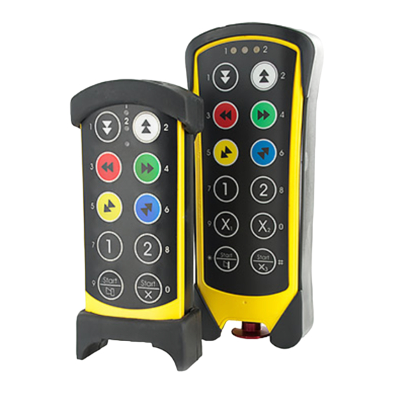
TRANSMITTER Pictures of the transmitter can be found on the fold-out page. Technical Specifications 860TX-10 860TX-12 Stop button Stop button 10 two way push buttons 12 two way push buttons Internal rechargeable battery External rechargeable battery Radio: PLL Synthesizer Radio: PLL Synthesizer 69 different frequencies, 433.075 - 434.775 MHz 69 different frequencies, 433.075 - 434.775 MHz Enclosure size: 160x70x35 mm... -
Page 8: Yellow Led
RECEIVER 860RX Pictures of the receiver can be found on the fold-out page. Technical Specifications Relay outputs: Midi: 10+2 for stop function, Maxi: 24+2 for stop function Stop relay: potential free, makes 8A AC1 Function relay: potential free, breaks/makes 16A AC1 Radio: PLL synthesizer 69 different frequencies, 433.075 - 434.775 MHz Size: 250x175x75 mm... -
Page 9: Installing The Receiver And The Receiver Antenna
CONNECTING THE RECEIVER 1 2 3 4 5 6 7 8 9 10 11 12 13 14 15 16 17 18 19 20 21 22 23 24 25 26 27 28 29 30 31 32 33 34 35 36 37 38 39 40 41 C NO NC C NO NC C NO NC C NO NC C NO NC C NO NC C NO NC C NO NC C NO NC C NO NC To utilize the safety of the system, be sure to use relays SR1, SR2 as stop relays in the safety circuitry of the... -
Page 10: Co-Programming The Transmitter And Receiver
CO-PROGRAMMING THE TRANSMITTER AND RECEIVER The receiver can be programmed to accept up to three different transmitters, where each transmitter has its own unique code.The LEDs 6 and 10 on the receiver indicate how many transmitters have been programmed in the receiver. Not flashing = No transmitter has been programmed 1 flash... -
Page 11: Yellow Led
DO THE FOLLOWING TO REPLACE A TRANSMITTER: 1. Check the ID-code on the transmitter that should be erased from the receiver. 2. Start-up the transmitter that should be programmed into the receiver.You must be in the working range of the receiver that should be erased and programmed. 3. -
Page 12: Green Led
3 modes.This is very useful when the 69 channel transmitter is used with a receiver with the 16+16 radio modul (old 860 version). If the 16+16 channel radio module is mounted in the transmitter it is not possible to select these modes. -
Page 13: Changing The Frequency
CHANGING THE FREQUENCY Programming/changing the frequency can only be carried out with the help of the transmitter. Decide which channel/frequency you wish to transmit on by using the table below before you start program- ming.The receiver automatically detects and changes to the new frequency. FREQUENCY TABLE (69 CHANNELS) CHANNEL FREQUENCY... - Page 14 FREQUENCY TABLE (16+16 CHANNELS) CHANNEL FREQUENCY STRAP CHANNEL FREQUENCY STRAP 434.650 MHz Open 434.625 MHz Closed 434.600 MHz Open 434.575 MHz Closed 434.550 MHz Open 434.525 MHz Closed 434.500 MHz Open 434.475 MHz Closed 434.450 MHz Open 434.425 MHz Closed 434.400 MHz Open 434.375 MHz...
-
Page 15: Yellow Led
STEP UP/DOWN IN FREQUENCY It is possible to move up or down in frequency before the transmitter is started-up. 1. Start the transmitter by pressing the start buttons for at least 1 second. 2. Release left start button, but hold right start button. 3. -
Page 16: Yellow Led 1
PIN CODE FUNCTION It is possible to program 10 PIN codes on each transmitter. PROGRAMMING A PIN CODE: 1. Start the transmitter by pressing the start buttons for at least 1 second. – The red LED 3 lights continuously. 2. Release left start button, but hold right start button. NOTE! You have 0.3 seconds to perform the action in step 3. -
Page 17: Yellow Led
ERASING ALL PIN-CODES You can, if necessary, erase all the PIN codes on the transmitter. ERASE ALL THE PIN CODES ON THE TRANSMITTER: 1. Start the transmitter by pressing the start buttons for at least 1 second. – The red LED 3 lights continuously. 2. -
Page 18: Function Selector
CODE TIME DELAY COMMENTS No time delay Sets the time delay in seconds 0,3s 0,5s 1,5s PROGRAMMING TIME DELAY BETWEEN PUSHBUTTONS 1. Start the transmitter by pressing the start buttons for at least 1 second. – The red LED 3 lights continuously. 2. - Page 19 No. of Function LED TX Function Receiver Function selector switch Comments functions selection (transmit- selection model (receiver) 4, 6, 7, 8. TX (trans- ter) RX (re- (Maxi or mitter) ceiver) Midi) 6x2+1x1 MIDI OFF.OFF.ON.OFF Receiver 1 (6x2+1x1) 6x2+1x1 MIDI ON.OFF.ON.OFF Receiver 2 (6x2+1x1) 6x2+1x1 MIDI...
-
Page 20: The Transmitter's Function Selections And Led Indications
THE TRANSMITTER’S FUNCTION SELECTIONS AND LED INDICATIONS It is possible to program the function selection on the transmitter.The two yellow LEDs on the transmitter indicate which receiver/receivers, relay group/groups or the lift on an overhead crane are to be controlled. By setting the receiver’s function selector switch at the same time a number of different types of relay functions can be selected (see chapter “The receiver’s function selection/relay functions“). -
Page 21: Yellow Led/Start-Up
6. Restart the transmitter by pressing the start buttons. YELLOW LED/START-UP If function selection 1 or 2 is programmed in 860 mode it is possible to choose which yellow LED/LED’s that should be on when starting the transmitter. Yellow LED start-up options, function selection 1: •... -
Page 22: The Receiver's Function Selection/Relay Functions
THE RECEIVER’S FUNCTION SELECTION/RELAY FUNCTIONS Program the function selection on the receiver: The function selection on the receiver is programmed by setting the function selector switches in either the ON or OFF positions.To see how the switches should be set refer to respective function selections or the function selection table. - Page 23 Function selection D: 860TX-10 860TX-12 Relay function: 8 single functions + 2 relays to indicate that the receiver is selected. Using the transmitter’s buttons 7 and 8 either receiver 1, 2 or both can be con- trolled. See figure D for which buttons control respective relays. Receiver 1: The function selector switch: 4=OFF, 6=OFF, 7=OFF, 8=OFF Relay 7 is activated when the yellow LED 1 is lit on the transmitter.
- Page 24 Function selection G: 860TX-10 860TX-12 Relay function: 4 double + 2 single functions (4x2+2x1). Using the transmitter’s buttons 7 and 8 either receiver 1, 2 or both can be controlled. See figure G for which buttons control respective relays. Receiver 1: The function selector switch: 4=OFF, 6=OFF, 7=OFF, 8=ON Receiver 2: The function selector switch: 4=ON, 6=OFF, 7=OFF, 8=ON...
- Page 25 Function selection J: 860TX-10 860TX-12 Relay function: 6 double + 1 single function (6x2+1x1) Using the transmitter’s buttons 7 and 8 receivers 1 or 2 can be control- led, but never both receivers simultaneously. See figure J for which buttons control respective relays.
- Page 26 Function selection M: 860TX-10 860TX-12 Relay function: 8/10 double functions + 2 relays to indicate that the receiver is selected. 1/11 2/12 1/11 2/12 Using the transmitter’s buttons 7 and 8 receivers 1 or 2 can be controlled, 3/13 4/14 3/13 4/14 but both receivers simultaneously.
- Page 27 Function selection P: 860TX-10 860TX-10 Relay function: 9+9/11+11 single functions + 2 relays to indicate the selected relay group. Using the transmitter’s button 10 you can select which relay group you want to control (1-9 or 11-19). See figure P for which buttons control respective relays.
-
Page 28: Momentary Or Latched Relay Functions
MOMENTARY OR LATCHED RELAY FUNCTIONS The system is supplied with an momentary function as the default setting. Program as set out below if you want a latched function. Momentary function: The relay only switches/activates during the period the button on the transmitter is pressed down. Latched/Toggling function: The position of the relay changes each time the button on the transmitter is pressed, but maintains its new position once the button has been released. - Page 29 Functions 3-4, 13-14 are blocked when pressed simultaneously. LED 3 = ON LED 4 = ON Function 15 has priority over 5, function 16 over 6. LED 5 = ON LED 6 = OFF Function 15 has priority over 5, function 16 over 6. Functions 5-6, LED 5 = OFF LED 6 = ON 15-16 are blocked when pressed simultaneously.
-
Page 30: Stop Function Selector
PROGRAMMING THE INTERLOCK: 1. Start the system. 2. On the receiver:Turn the function selector switch 3 to the ON position. – All the relays in the receiver are disconnected and the red LEDs for respective relays go out. 3. On the transmitter: program by pressing the buttons (LED) defined as ON in the table ”Interlock”. Example: LED 5 = OFF and LED 6 = ON, is programmed by pressing button 6 on the transmitter, the LEDs will then light according to the required interlock option The red LEDs will light continuously above the relays you have chosen. -
Page 31: Trouble Shooting
Please contact your dealer if you have followed these instructions and despite this have not managed to get the radio system to work. DISPOSAL The 860, any accessories and all replaced parts must be disposed of and recycled in accordance with the local environmental regulations regarding the disposal of used equipment and waste. -
Page 32: Settings Form: Receiver And Transmitter
0________ ________________________________ 1________ ________________________________ 2________ ________________________________ 3________ ________________________________ 4________ ________________________________ 5________ ________________________________ 6________ ________________________________ “ EC Declaration of Conformity for Tele Radio radio 7________ ________________________________ remote control systems can be found at http://www. tele-radio.com” 8________ ________________________________ 9________ ________________________________ 0________ ________________________________... - Page 33 APPENDIX 15.19 - TWO PART WARNING STATEMENT THIS DEVICE COMPLIES WITH PART 15 OF THE FCC RULES. OPERATION IS SUBJECT TO THE FOLLO- WING TWO CONDITIONS: (1) THIS DEVICE MAY NOT CAUSE HARMFUL INTERFERENCE, AND (2) THIS DEVICE MUST ACCEPT ANY INTERFERENCE RECEIVED, INCLUDING INTERFERENCE THAT MAY CAUSE UNDESIRED OPERATION.
- Page 34 Loiblstrasse 4 Huvudkontor, Datavägen 21, SE-436 32 Askim, Sverige D-84069 Schierling Deutschland Tel. +46 (0)31 748 54 60 Fax +46(0)31 68 54 64 Tel +49 (0)94 51-94 91 11 e-post info@tele-radio.com Fax +49 (0)94 51-94 91 44 www.tele-radio.com e-post kontakt@tele-radio.com P.O Box 67 c/o Cervis Incorp.
Need help?
Do you have a question about the 860 and is the answer not in the manual?
Questions and answers