Black Horse Model Sea Fury BH102 Instruction Manual Book
Hide thumbs
Also See for Sea Fury BH102:
- Instruction manual (35 pages) ,
- Instruction manual book (30 pages)
Table of Contents
Advertisement
Quick Links
Download this manual
See also:
Instruction Manual
Instruction Manual book
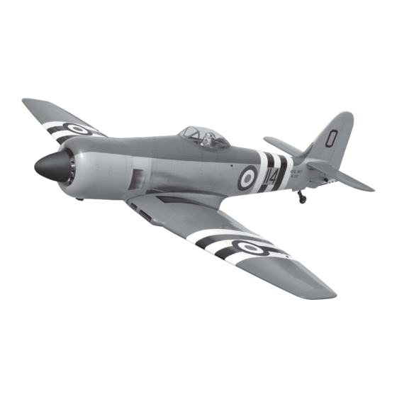
SPECIFICATION
Wingspan : 1,950 mm
Length
Weight
Radio
Servo
Engine
: 1,757 mm
: 6.8 kg
: 06 channels.
: 10 standard high torque servos
: O.S GT 33cc gas(35cc gas FUJI IMVAC).
ITEM CODE:BH102.
76.77 in.
69.17 in.
14.96 Lbs.
Made in Vietnam.
Advertisement
Table of Contents

Subscribe to Our Youtube Channel
Related Manuals for Black Horse Model Sea Fury BH102


Summary of Contents for Black Horse Model Sea Fury BH102
- Page 1 Instruction Manual book ITEM CODE:BH102. SPECIFICATION Wingspan : 1,950 mm 76.77 in. Length : 1,757 mm 69.17 in. Weight : 6.8 kg 14.96 Lbs. Radio : 06 channels.
- Page 2 Item code:BH102 SEA FURY - INSTRUCTION MANUAL. This instruction manual is designed to help you build a great flying aeroplane. Please read this manual thoroughly before starting assembly of your SEA FURY. Use the parts listing below to identify all parts. WARNING.
-
Page 3: Safety Precaution
Item code:BH102 SEA FURY - INSTRUCTION MANUAL. Caution: this model is not a toy! If you are a beginner to this type of powered model, please ask an experienced model flyer for help and support. If you attempt to operate the model without knowing what you are doing you could easily injure yourself or somebody else. -
Page 4: Installing The Aileron Servos
Item code:BH102 SEA FURY - INSTRUCTION MANUAL. REPLACEMENT SMALL PARTS 5x40mm. 1.Air retract main gear. 2.Door mounting wheel. 3.Wheels. I. AILERON. 4.Mount wood of Air tank. 1.INSTALLING THE AILERON SERVOS. 5. Air tank. 1) Install the rubber grommets and brass ... - Page 5 Item code:BH102 SEA FURY - INSTRUCTION MANUAL. Secure Aileron 2) Using a modeling knife, remove the cov- ering at possition show below. Thread 5. Instal servo tray with aileron servo into the wing as same as picture below. Remove covering Servo tray.
-
Page 6: Installing The Aileron Linkages
Item code:BH102 SEA FURY - INSTRUCTION MANUAL. 2.INSTALLING THE AILERON 3.INSTALLING THE AILERON CONTROL HORN. LINKAGES. Control horn of Aileron Installing the aileron linkages as pictures below. 3x10mm. 70mm 3x10mm Secure. PLUS glue EPOXY EPOXY PLUS glue Repeat the procedure for the other wing half. - Page 7 Item code:BH102 SEA FURY - INSTRUCTION MANUAL. 2.INSTALLING THE FLAP CONTROL HORN. Control horn of Flap. tray servo Electric EPOXY wire PLUS glue Thread 2x10mm. Control horn of the flap Secure. 3.INSTALLING THE FLAP LINKAGES . 3x10mm. 70mm.
- Page 8 Item code:BH102 SEA FURY - INSTRUCTION MANUAL. Secure. Bottom side. Aileron. Flap. Repeat the procedure for the other wing half. INSTALLING AIR RETRACTABLE LANDING GEAR. 3x15mm 5x40mm...
- Page 9 Item code:BH102 SEA FURY - INSTRUCTION MANUAL. 3x15mm 5x40mm Secure.
- Page 10 Item code:BH102 SEA FURY - INSTRUCTION MANUAL. Secure 3x4mm 3x4mm 3x6mm 3x6mm 3x6mm 3x4mm...
- Page 11 Item code:BH102 SEA FURY - INSTRUCTION MANUAL. Bottom side Drill a hole 3mm diameter Repeat the procedure for the other wing half. INSTALLING THE ENGINE MOUNT AND AIR TANK. See pictures below: S e c u r e 3x4mm Drill a hole Secure 6mm diameter 3x6mm...
-
Page 12: Installing The Engine Mount
Item code:BH102 SEA FURY - INSTRUCTION MANUAL. Air tank C/A gue INSTALLING THE ENGINE MOUNT. See pictures below: 5x70mm Air tank Secure. Air tank Left side... -
Page 13: Installing The Stopper Assembly
Item code:BH102 SEA FURY - INSTRUCTION MANUAL. FUEL TANK. INSTALLING THE STOPPER ASSEMBLY 1) The stopper has been pre-assembled at the factory. Tygon gas tubing not included. 2) Using a modeling knife, cut one length of silicon fuel line (the length of silicon fuel line Fuel pick- up tube Vent tube is calculated by how the weighted clunk should... -
Page 14: Installing The Throttle - Cable
Item code:BH102 SEA FURY - INSTRUCTION MANUAL. INSTALLING THE THROTTLE - CABLE. 1. Install one adjustable metal connector through the third hole out from the center of one servo arm, enlarge the hole in the servo arm using a 2mm drill bit to accommodate the servo connector. - Page 15 Item code:BH102 SEA FURY - INSTRUCTION MANUAL. P u s h r o d Left side Choke. cut off cable P u s h r o d excess Choke. E l e c t r i c Power. Left side. Pushrod Choke.
- Page 16 Item code:BH102 SEA FURY - INSTRUCTION MANUAL. 4. Install the muffler and muffler extension COWLING. onto the engine and make the cutout in the 1. Slide the fiberglass cowl over the en- cowl for muffler clearance. Connect the fuel gine and line up the back edge of the cowl with and pressure lines to the carburetor , muffler the marks you made on the fuselage.
-
Page 17: Installing The Spinner
Item code:BH102 SEA FURY - INSTRUCTION MANUAL. INSTALLING THE SPINNER. Install the spinner backplate, propeller and spinner cone. The spinner cone is held in place using two 3mm x 8mm machine screws. Secure. M a c h i n e screw. -
Page 18: Horizontal Stabilizer
Item code:BH102 SEA FURY - INSTRUCTION MANUAL. ELEVATOR INSTALLATION. SERVO INSTALLATION. 1. Install the rubber grommets and brass collets into the elevator servo. Test fit the servo into the servo tray. 2. Mount the servo to the tray using the ... -
Page 19: Elevator Control Horn Installation
Item code:BH102 SEA FURY - INSTRUCTION MANUAL. ELEVATOR CONTROL HORN INSTALLATION. Elevator control horn install as same as the way of aileron control horn. Please see pic- tures below. A+B Epoxy PLus glue Bottom side. 3x10mm Elevator control horn ELEVATOR PUSHROD INSTALLATION. Elevator pushrod install as same as the way ... - Page 20 Item code:BH102 SEA FURY - INSTRUCTION MANUAL. Bottom side E l e v a t o r E l e v a t o r pushrod. pushrod. bend 90 degree. 3x10mm Secure. E l e v a t o r pushrod.
-
Page 21: Rudder Installation
Item code:BH102 SEA FURY - INSTRUCTION MANUAL. RUDDER INSTALLATION. Please see pictures below. Aluminium Snap keeper. VERTICAL INSTALLATION. Rudder servo install as same as method of elevator servo. See picture below: Push. Rudder servo Top side R u d d e r servo... -
Page 22: Rudder Control Horn Installation
Item code:BH102 SEA FURY - INSTRUCTION MANUAL. A+B PLUS Glue. Aluminium Aluminium Bottom side. RUDDER CONTROL HORN INSTALLATION. Rudder control horn install as same as the way of aileron control horn. Please see pic- tures below. Control horn of Rudder . Cut. -
Page 23: Mounting The Tail Wheel Bracket
Item code:BH102 SEA FURY - INSTRUCTION MANUAL. Bottom side. Bottom side. MOUNTING THE TAIL WHEEL BRACKET. 3x15mm R u d d e r control RUDDER CABLE INSTALLATION. Rudder push-pull system install as sams as picture below 3x10mm Secure. R u d d e r cable. - Page 24 Item code:BH102 SEA FURY - INSTRUCTION MANUAL. 1. Secure the tail wheel bracket in place R e m o v e using four 3mm x 15mm screws. Be careful covering. not to overtighten the screws. 3x15mm Epoxy glue.
- Page 25 Item code:BH102 SEA FURY - INSTRUCTION MANUAL. C/A glue. Rudder cable. Elevator pushrod. Bottom side. C/A glue C/A glue Plastic parts of elevator pushrod. B o t t o m side. Cut.
- Page 26 Item code:BH102 SEA FURY - INSTRUCTION MANUAL. Top side. INSTALLATION SERVO WHEEL DOOR. Bottom side. Rudder cable...
- Page 27 Item code:BH102 SEA FURY - INSTRUCTION MANUAL. tray servo. 3x15mm Secure. Secure.
- Page 28 Item code:BH102 SEA FURY - INSTRUCTION MANUAL. Air tank Air supply Valve one way Right main gear wing Left main gear wing Control Valve Secure. bottom side INSTALLATION SERVO USING FOR VALVE CONTROL Servo valve control. Connector Servo valve control.
- Page 29 Item code:BH102 SEA FURY - INSTRUCTION MANUAL.
-
Page 30: Installing The Switch
Item code:BH102 SEA FURY - INSTRUCTION MANUAL. INSTALLING THE SWITCH. 1) Cut out the switch hole using a modeling knife. Use a 2mm drill bit and drill out the two Tie wrap. mounting holes through the fuselage side. 2) Secure the switch in place using the ... - Page 31 Item code:BH102 SEA FURY - INSTRUCTION MANUAL. 3.Insert two wing panels as pictures be- low. Left wing. 2. Attach the aluminium tube into the fuselage. Right side. Secure...
-
Page 32: Installing Cockpit Fuselage
Item code:BH102 SEA FURY - INSTRUCTION MANUAL. Secure. C/A glue. INSTALLING COCKPIT FUSELAGE . See picture below: A+ B Epoxy PLUS glue. C/A glue. - Page 33 Item code:BH102 SEA FURY - INSTRUCTION MANUAL. BALANCING. C/A glue. 1) It is critical that your airplane be bal- anced correctly. Improper balance will cause your plane to lose control and crash. THE CENTER OF GRA VITY IS LOCA TED 138MM BACK FROM THE LEADING EDGE OF THE WING.
-
Page 34: Control Throws
Item code:BH102 SEA FURY - INSTRUCTION MANUAL. CONTROL THROWS. 1) We highly recommend setting up a plane using the control throws listed. 2) The control throws should be meas- ured at the widest point of each control sur- face.
Need help?
Do you have a question about the Sea Fury BH102 and is the answer not in the manual?
Questions and answers