Table of Contents
Advertisement
Quick Links
Advertisement
Table of Contents

Related Manuals for FAAC E145


Summary of Contents for FAAC E145
- Page 1 www.metalines.com sales@metalines.com...
-
Page 2: Ce Declaration Of Conformity
CE DECLARATION OF CONFORMITY Manufacturer Address Declares that www.metalines.com sales@metalines.com... -
Page 3: Warnings For The Installer
WARNINGS FOR THE INSTALLER www.metalines.com sales@metalines.com... -
Page 4: Table Of Contents
CE DECLARATION OF CONFORMITY ..................2 WARNINGS FOR THE INSTALLER ...................3 1. TECHNICAL SPECIFICATIONS ....................5 2. PREPARING FOR INSTALLATION ..................6 3. BOARD LAYOUT ........................6 4. ELECTRICAL CONNECTIONS .....................8 4.1 J1 - Mains primary Power Supply ...................8 4.2 J2 - Motors and Flashing lamp ..................8 4.3 J3 - Low-voltage accessories - inputs/outputs .............9 4.4 J12 - programmable outputs - electric locks ..............10 4.5 J12 -J6 - LIMIT SWITCH AND... -
Page 5: Technical Specifications
CONTROL BOARD E145 FAAC 1. TECHNICAL SPECIFICATIONS PURPOSE: supply switching system Tab. Mains primary power supply Power absorbed from mains PC/MAC FUNCTION THAT CAN BE ENABLED FROM A MAX load for motors Accessories power supply MAX. accessories current Operating ambient temperature... -
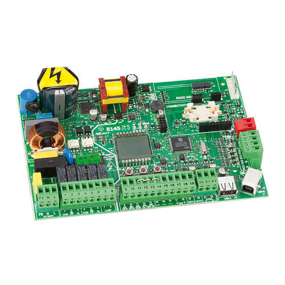
Page 6: Preparing For Installation
2. PREPARING FOR INSTALLATION For safety reasons, it is important for people to carefully follow all the warnings and instructions contained in this manual. Incorrect installation or incorrect use of the product can cause serious harm to people. Before proceeding with product installation, carefully read the entire manual. - Page 7 DL16 Microprocessor +24V SW1 +/R1 DL17 SW2 -/R2 90V~ 260V~ SW3 F FCC2 FCA2 FCC1 Channel 1 OPEN A FCA1 Channel 2 OPEN B XF433/XF868 ( Channel 1 OPEN A Channel 2 OPEN B DL10 USB DL11 RADIO1-XF DL12 RADIO2-XF DL13 ERROR BUS MON BAT1...
-
Page 8: Electrical Connections
4. ELECTRICAL CONNECTIONS 12V ~ 12V ~ 230V~ 90V~ MAX 60W 260V~ 50/60 Hz Mot1 Mot2 PE N L 1 2 3 4 5 6 7 8 9 10 11 12 13 14 15 16 17 18 19 20 21 22 Photocells and safety de- vices: for connections, see the related paragraph. -
Page 9: J3 - Low-Voltage Accessories - Inputs/Outputs
4.3 J3 - LOW-VOLTAGE ACCESSORIES - INPUTS/OUTPUTS TOTAL opening opening PARTIAL opening on 2-motor systems = 100% of leaf 1 opening; on 1-motor systems = 50% of leaf 1 opening. PARTIAL opening b bC C CLOSE OPEN B CLOSE - N.O. To install more than one OPEN A or OPEN B pulse generator, connect the N.O. -
Page 10: J12 - Programmable Outputs - Electric Locks
4.4 J12 - PROGRAMMABLE OUTPUTS - ELECTRIC LOCKS indicator light disabled leaf 1 enabled leaf 2 Other programming options are available by programming via a PC/MAC (see dedicated instructions). 4.5 J12 -J6 - LIMIT SWITCH AND GATECODER disabled If no limit switches are used, you DO NOT need to jumper the limit switch contacts FCC1, FCA1, FCC2, FCA2. -
Page 11: J10 - Bus-2Easy Accessories
4.6 J10 - BUS-2EASY ACCESSORIES BUS-2EASY If no BUS-2EASY accessories are used, leave the BUS-2EASY connector free. BUS-2EASY photocells Photocells during closing: Photocells during opening: Photocells during opening/closing: Pulse generators: www.metalines.com sales@metalines.com... - Page 12 Address assignment of BUS-2EASY photocells The transmitter and receiver of a pair of photocells must have the same DIP-SWITCH setting. Two or more pairs of photocells must not have the same DIP-SWITCH setting. Other programming options are available by programming via a PC/MAC (see dedicated instructions).
- Page 13 BUS-2EASY encoder Connection - Address assignment of BUS-2EASY Encoder The polarity of the BUS-2EASY line connection determines the correspondence of the encoder to one leaf or the other. pay careful attention to the indications of the status LEDs located on the body of each encoder.
-
Page 14: J5 - Xf Module Rapid Connector
Tab. BUS-2EASY FLASHING Power present Power present Power absent Communication present Communication absent Communication absent DL1 must always be on to confirm correct encoder/board connection. Leaf 1 Leaf 2 DL2 indicates the leaf on which the encoder is installed; it must be on for leaf 1 and off for leaf 2. -
Page 15: Traditional Photocells
4.10 TRADITIONAL PHOTOCELLS Closing photocells: Opening photocells: Photocells for opening/closing: Pulse generators: Fail Safe function o1 01 With Fail Safe disabled: connect the transmitter (TX) power supply to terminals 15 and 18 of J3. With Fail Safe enabled: connect the power supply negative of the transmitters (TX) to OUT1. - Page 16 FAIL SAFE disabled FAIL SAFE enabled 9 10 11 12 13 14 15 16 17 18 19 20 21 22 9 10 11 12 13 14 15 16 17 18 19 20 21 22 IN1 IN2 IN3 IN4 IN5 IN1 IN2 IN3 IN4 IN5 OUT1 OUT2 LK1 LK2 OUT1 OUT2 LK1 LK2 OP-A OP-B STOP CL FSW OP...
- Page 17 FAIL SAFE disabled FAIL SAFE disabled 20 21 22 9 10 11 12 13 14 15 16 17 18 19 9 10 11 12 13 14 15 16 17 18 19 20 21 22 IN1 IN2 IN3 IN4 IN5 IN1 IN2 IN3 IN4 IN5 OUT1 OUT2 LK1 LK2 OUT1 OUT2 LK1 LK2 OP-A OP-B STOP CL FSW OP...
-
Page 18: Programming
5. PROGRAMMING programming using a PC • BASIC programming • ADVANCED programming Tab. Changing the values is effective imme- diately, while the final memorisation must be carried out upon exiting programming fault PASSWORD Notes The default password is 0000. EXIT programming at anytime The programming using a PC/MAC, with a modi- fied PASSWORD (different from the default one), will inhibit the programming by board. -
Page 19: Basic Programming Functions
5.1 BASIC PROGRAMMING FUNCTIONS Display Basic Function Default MOTOR TYPE: DEFAULT: FUNCTION LOGICS: b bC C For a description of how the logics operate, see the related paragraph. www.metalines.com sales@metalines.com... - Page 20 Display Basic Function Default PAUSE A TIME (visualised only with Automatic logics) TOTAL 00 59 e.g.: if the display shows , the time is 2 min and 50 sec. PAUSE TIME B (visualised only with Automatic logics): PARTIAL 00 59 Es: if the display shows , the time is 2 min and 50 sec.
- Page 21 Display Basic Function Default MOTOR 1 POWER: If the power is modified, we recommend performing a new SETUP - see the related paragraph. If hydraulic motors are used, power must be programmed to maximum level MOTOR 2 POWER (visualised only with the function If the power is modified, we recommend performing a new SETUP - see the related paragraph.
- Page 22 Display Basic Function Default LIMIT SWITCH WHEN CLOSING (displayed only if function In case of mixed configuration ( ) this function works only on the swing-leaf. The limit switch on the SLIDING leaf is required and determines when the leaf stops. After having changed the value of this function, SETUP is required: the card will signal error (configuration error) until the SETUP is...
- Page 23 Display Basic Function Default MOTOR 2 dead-man DRIVE mode (visualised only with the function +/ R1 -/ R2 MOTOR 1 dead-man DRIVE mode +/ R1 -/ R2 WORK TIME LEARNING (SETUP): See the related paragraph. AUTOMATED SYSTEM STATUS: automated system status WARNING If power is lost to the board prior to confirmation (step 2.), all changes made will be lost.
-
Page 24: Advanced Programming Functions
= enabled (for 2 sec) = disabled In case of systems with an absolute encoder, to enable this function a setup must be performed using the automatic leaf stop on the mechanical contact point. E145 732784 - Rev. A www.metalines.com sales@metalines.com... - Page 25 Display Advanced Function Default DELAY FOR OPENING LEAF (visualised only with the function 00 59 e.g.: if the display shows , the time is 1 min and 20 sec. LEAF 1 DECELERATION: 00 99 LEAF 2 DECELERATION (visualised only with the function 00 99 PRE-FLASHING: www.metalines.com...
- Page 26 Display Advanced Function Default CLOSING PHOTOCELLS: ADMAP FUNCTION: ANTI-CRUSHING SENSITIVITY (visualised only with the function MECHANICAL STOP SEARCH ANGLE (displayed only if function and functions or = 0.3 20 0.3 9.9 10 20 ADDITIONAL OPERATING TIME (displayed only if function functions or = 0 30...
- Page 27 Display Advanced Function Default flashing DISABLED is displayed, it indicates that the output is used as a TIMER set from the PC/MAC software. OUT 1 TIMING (visualised only with the function 1 59 1 59 OUT 2: See the options as OUT 2 TIMING (visualised only with the function Adjustable as for...
- Page 28 Display Advanced Function Default X-COM RADIO MODULE RESET and ACQUISITION: X-COM module is used for radio communication between the boards and the PC/MAC. Before enabling communication, the X-COM module must be configured. MAINTENANCE REQUEST - CYCLE COUNTER (linked to the subsequent functions): If using a PC/MAC a maintenance request is set with a number of cycles greater than 99,990, the subsequent two functions...
- Page 29 Display Advanced Function Default CYCLE PROGRAMMING (TENS): AS Y 0 99 AS no e.g.: if the system has performed 11,218 cycles, = 11 and = 21 will be displayed AUTOMATED SYSTEM STATUS: automated system status WARNING If power is lost to the board prior to confirmation (step 2.), all changes made will be lost.
-
Page 30: Bus-2Easy Device Installation
BUS-2EASY DEVICE INSTALLATION ELECTRICAL CONNECTIONS 5.6.1 BUS-2EASY DEVICE ENTRY (see the figure) If no BUS device has ever been entered in the board, the display will read Opening photocells Encoder 1 Opening photocells and Closing photocells BUS Status Encoder 2 OPEN photocell Closing photocells Fig. - Page 31 Fig. Encoder Photocells Encoder Photocells Checking the securing devices entered on the board +/ R1 LED DL15 (Red) LED DL14 (Green) ON steady Slow blinking (blink every 2,5 sec) Rapid blinking (blink every 0.5 sec) www.metalines.com sales@metalines.com...
-
Page 32: Time Learning - Setup
5.4 TIME LEARNING - SETUP During SETUP, the connected BUS-2EASY accessories are always entered. BUS-2EASY encoders entered by the SETUP must always be enabled using the para- meter (BASIC Programming). During SETUP all safety devices are disabled! Therefore, carry out the operation avoiding any transit in the leaf movement area. -
Page 33: Testing The Automated System
Operation WITHOUT Encoder Operation WITH Encoder Operation WITHOUT Encoder Operation WITH Encoder Steps 6 and 7 with function (the limit switch determines the stopping of motion) the OPEN A pulse for stopping motion is ignored. (the limit switch determines the start of deceleration) send an OPEN A pulse only after involving the closing limit switch. -
Page 34: Memorising The Radio Code
6. MEMORISING THE RADIO CODE The different types of radio code (DS, SLH/SLH LR, LC/RC) can coexist simultaneously on the two channels. You can enter up to 1600 radio codes divided between OPEN A and OPEN B/CLOSE. To use different encoding systems on the same channel, you must complete the learning of each encoding system and then repeat the procedure for the other one. -
Page 35: Memorising Lc/Rc Radio Controls (Only 433 Mhz)
Ensure that there are no obstacles (by people or things) during the automated system movement. 6.2 MEMORISING LC/RC RADIO CONTROLS (ONLY 433 MHZ) www.metalines.com sales@metalines.com... -
Page 36: Memorising Ds Radio Controls
6.2.1 REMOTE MEMORISATION OF LC/RC RADIO CONTROLS 6.3 MEMORISING RADIO CONTROLS www.metalines.com sales@metalines.com... -
Page 37: Deleting The Radio Controls
6.4 DELETING THE RADIO CONTROLS This operation CANNOT be reversed. This will delete ALL the radio control codes me- morised as both OPEN A and OPEN B/CLOSE. The cancellation procedure is active only in gate status visualisation mode. -/ R2 - / R2 www.metalines.com sales@metalines.com... -
Page 38: Start-Up
7. START-UP 7.1 CHECKING THE LEDs = contact closed = contact open ED ON ED OFF RP/DEC RP/DEC RADIO 1 R ADI O 1 DL11 D L1 1 RADIO 2 R ADI O 2 DL12 D L1 2 BAT1 B AT 1 CR2032 CR2032 ERROR... -
Page 39: Signalling Errors And Alarms
8. SIGNALLING ERRORS AND ALARMS ERRORS ALARMS These warnings will disappear in the following cycle only if the situation causing them is removed. 8.1 ERRORS When there is an ERROR the ERROR LED will go on steady. By simultaneously pressing and - the display will show the corresponding error number. -
Page 40: Alarms
8.2 ALARMS When there is an ALARM the ERROR LED will begin to flash. By simultaneously pressing + and - the display will show the corresponding alarm number. N° ALARM Solution/Description www.metalines.com sales@metalines.com... -
Page 41: Troubleshooting
9. TROUBLESHOOTING Description Solution www.metalines.com sales@metalines.com... -
Page 42: Managing The Configuration File - J8 Usb
10. MANAGING THE CONFIGURATION FILE – J8 USB E145SW.bin E145.trm E145.prg E145.rad • E145SW.bin • E145.trm • E145.prg • E145.rad F for Display Function Default BOARD SOFTWARE UPGRADE: E145SW.bin USB DL10 The upgrade is carried out correctly only if the USB memory contains a valid file named exactly E145SW.bin... - Page 43 BOARD CONFIGURATION UPGRADE: E145.prg USB DL10 The upgrade is carried out correctly only if the USB memory contains a valid file named exactly E145.prg TIMER CONFIGURATION UPGRADE: E145.trm USB DL10 The upgrade is carried out correctly only if the USB memory contains a valid file named exactly E145.trm...
- Page 44 Display Function Default BOARD CONFIGURATION DOWNLOAD: E145_xxx.prg E145.prg by overwriting BOARD TIMER DOWNLOAD: E145_xxx. E145.trm by overwriting BOARD RADIO CODE DOWNLOAD: E145_xxx.rad E145.rad by overwriting www.metalines.com sales@metalines.com...
-
Page 45: Function Logics
11. FUNCTION LOGICS Automated system Automated system Status: photocell LOGIC status: stopped status: in motion involvement www.metalines.com sales@metalines.com... - Page 46 www.metalines.com sales@metalines.com...
- Page 47 SEMI AUTOMATIC LOGIC PULSES AUTOMATED SYSTEM OPEN A OPEN B CLOSE STOP FSW OP FSW CL FSW CL STATUS CLOSED OPENING OPEN CLOSING STOPPED “ ” SEMI AUTOMATIC STEP STEP LOGIC PULSES AUTOMATED SYSTEM OPEN A OPEN B CLOSE STOP FSW OP FSW CL FSW CL...
- Page 48 “ ” AUTOMATIC SAFETY LOGIC PULSES AUTOMATED SYSTEM OPEN A OPEN B CLOSE STOP FSW OP FSW CL FSW CL STATUS CLOSED OPENING OPEN IN PAUSE CLOSING STOPPED “ ” AUTOMATIC SAFETY WITH IN PAUSE REVERSING LOGIC PULSES AUTOMATED SYSTEM OPEN A OPEN B CLOSE...
- Page 49 “ ” “ ” AUTOMATIC SAFETY STEP STEP LOGIC PULSES AUTOMATED SYSTEM OPEN A OPEN B CLOSE STOP FSW OP FSW CL FSW CL STATUS CLOSED OPENING OPEN IN PAUSE CLOSING STOPPED AUTOMATIC LOGIC PULSES AUTOMATED SYSTEM OPEN A OPEN B CLOSE STOP FSW OP...
- Page 50 AUTOMATIC LOGIC PULSES AUTOMATED SYSTEM OPEN A OPEN B CLOSE STOP FSW OP FSW CL FSW CL STATUS CLOSED OPENING OPEN IN PAUSE CLOSING STOPPED “ ” AUTOMATIC STEP STEP LOGIC PULSES AUTOMATED SYSTEM OPEN A OPEN B CLOSE STOP FSW OP FSW CL FSW CL...
- Page 51 AUTOMATIC WITH TIMER FUNCTION LOGIC PULSES AUTOMATED SYSTEM OPEN A OPEN B CLOSE STOP FSW OP FSW CL FSW CL STATUS CLOSED OPENING OPEN IN PAUSE CLOSING STOPPED “ ” SEMI AUTOMATIC LOGIC OPEN B INPUTS BECOME CLOSE PULSES AUTOMATED SYSTEM OPEN A OPEN B...
- Page 52 MIXED LOGIC B IN OPENING C IN CLOSING OPEN B INPUTS BECOME CLOSE PULSES FOR OPENING DEAD PULSES COMMANDS FOR CLOSING AUTOMATED SYSTEM OPEN A OPEN B CLOSE STOP FSW OP FSW CL FSW CL STATUS CLOSED OPENING OPEN CLOSING STOPPED DEAD MAN LOGIC...
- Page 53 www.metalines.com sales@metalines.com...
- Page 54 www.metalines.com sales@metalines.com...
- Page 55 www.metalines.com sales@metalines.com...
- Page 56 SEDE - HEADQUARTERS FAAC S.p.A. ASSISTENZA IN ITALIA SEDE MILANO PADOVA ROMA TORINO FIRENZE SUBSIDIARIES AUSTRIA GERMANY BENELUX AUSTRALIA INDIA SWITZERLAND CHINA NORDIC REGIONS POLAND UNITED KINGDOM SPAIN RUSSIA FRANCE U.S.A. MIDDLE EAST www.metalines.com sales@metalines.com...
Need help?
Do you have a question about the E145 and is the answer not in the manual?
Questions and answers