Advertisement
Quick Links
Advertisement

Related Manuals for Forcepoint 6205


Summary of Contents for Forcepoint 6205
- Page 1 Next Generation Firewall Hardware Guide Model 6205 Revision B...
- Page 2 On the Forcepoint support website, you can find information about a released product, including product documentation, technical articles, and more. You can get additional information and support for your product on the Forcepoint support website at https://support.forcepoint.com. There, you can access product documentation, Knowledge Base articles,...
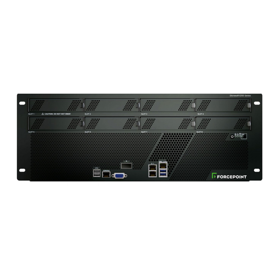
- Page 3 Forcepoint Next Generation Firewall 4U Hardware Guide Model 6205 features The figures and tables show the appliance components. 6205 front panel Interface module slots The upper slots are numbered 1—4 from left to right. The lower slots are numbered 5—8 from left to right.
- Page 4 Forcepoint Next Generation Firewall 4U Hardware Guide 6205 back panel Fans The upper fans are numbered 1, 3, and 5 from left to right. The lower fans are numbered 2, 4, and 6 from left to right. Power supplies 1—2 The upper power supply is 2.
- Page 5 Forcepoint Next Generation Firewall 4U Hardware Guide Component Slot number Port numbers Interface module 1–8. Slots 1–4 are on the upper row, and The port numbers start from 0 and increase ports slots 5–8 are on the lower row. from left to right. For example, the port farthest to the left in slot 1 is eth1_0.
- Page 6 When lit blue, an SSD is in the bay. Disk indicator When flashing blue, indicates SSD activity. Supported interface modules Forcepoint NGFW appliances support copper, fiber, and small form-factor pluggable (SFP) modules. Note: Do not remove any stickers from modules — they contain important information.
- Page 7 4 port gigabit Ethernet SFP module MOGF4 4 port 10 gigabit Ethernet SFP+ module revision 2 MOE10F4 Copper interface modules Forcepoint NGFW appliances support these copper interface modules. MO102 module The MO102 module is a two-port 10 gigabit copper interface module. Number Component...
- Page 8 Forcepoint Next Generation Firewall 4U Hardware Guide Number Component Color Description Link speed indicator Yellow 1 Gbps link. Green 10 Gbps link. MOG4B module The MOG4B module is a quad-port gigabit bypass copper module. Number Component Color Description Release lever...
- Page 9 1 Gbps link. Green 100 Mbps link. Unlit 10 Mbps link. Release lever Fiber interface modules Forcepoint NGFW appliances support these fiber interface modules. MO10S2B module The MO10S2B module is a two-port 10 gigabit bypass fiber module. Number Component Color Description...
- Page 10 Link speed/bypass/disconnect indicator Blue 10 Gbps link. Green Flashes in bypass mode. SFP interface modules Forcepoint NGFW appliances support these SFP interface modules. MO10F2 module The MO10F2 module is a two-port 10 gigabit SFP+ interface module. Number Component Color Description...
- Page 11 Forcepoint Next Generation Firewall 4U Hardware Guide MO40F2 module The MO40F2 module is a two-port 40 gigabit QSFP+ interface module. Number Component Color Description Release lever Activity/link/link speed indicator Green 40 Gbps link (other speeds not supported), flashes on activity.
- Page 12 Link speed indicator Blue 10 Gbps link. Precautions The precautions provide safety guidance when working with Forcepoint appliances and electrical equipment. Safety precautions Read the safety information and follow the procedures whenever you are working with electronic equipment. General safety Follow these rules to ensure general safety.
- Page 13 The power supply cable must include a grounding plug and must be plugged into a grounded electrical outlet. Power supply safety precautions Depending on the type of power supply that your Forcepoint NGFW appliance uses, different safety precautions and installation guidelines apply.
- Page 14 Forcepoint Next Generation Firewall 4U Hardware Guide • The case of the appliance must be grounded using the power connector pin or the grounding nut. We recommend using both grounding methods. • The mains supply plug on the power supply cable is the disconnect device on the appliance. To disconnect the appliance, you must first disconnect the mains, then disconnect the ground.
- Page 15 Forcepoint Next Generation Firewall 4U Hardware Guide Install a 6205 appliance in a two-post rack Use the short rack-mounting brackets to secure the appliance in the rack. Steps Attach a short bracket to each side of the appliance with one screw through each of the two grooves.
- Page 16 Forcepoint Next Generation Firewall 4U Hardware Guide Install a 6205 appliance in a four-post rack Attach the appliance to the front posts of the rack, and optionally use the long rack-mounting brackets to attach the appliance to the back posts of the rack.
- Page 17 Forcepoint Next Generation Firewall 4U Hardware Guide Attach the front panel to the front posts of the rack with two screws in each post. Result Figure 1: If attached to front and back posts of the rack...
- Page 18 Forcepoint Next Generation Firewall 4U Hardware Guide Figure 2: If attached to front posts of the rack only Install the SSD Install the SSD if it is not already installed. There are two SSD slots on the back panel of the appliances. Use only one SSD.
- Page 19 Forcepoint Next Generation Firewall 4U Hardware Guide Install an interface module If needed, install any interface modules. Before you begin • Read the safety precautions. • Make sure any interface modules you install are the correct type for your appliance.
- Page 20 IDs for the new ports start from the next free interface ID number. Use the new interface IDs to configure new interfaces in the Management Client, then refresh the policy on the engine to transfer the changes. See the Forcepoint Next Generation Firewall Product Guide for more information. CAUTION: Do not select the...
- Page 21 To use the serial console after the initial configuration on these appliances, use the command sg-bootconfig on the engine command line. For more information, see Command line tools in the Forcepoint Next Generation Firewall Product Guide for more information.
- Page 22 Forcepoint Next Generation Firewall 4U Hardware Guide Connect network cables to SFP ports If you installed an SFP interface module on the appliance or the appliance has an integrated SFP port, insert the copper or fiber-optic SFP transceiver into the port, then connect the cables.
- Page 23 Enter the command halt. Replace the power supply The power supplies are replaceable on most Forcepoint NGFW appliances. The power supplies are hot-swappable. CAUTION: Do not open the casing of a power supply module. Power supply modules can only be repaired by a qualified technician from the manufacturer.
- Page 24 Forcepoint Next Generation Firewall 4U Hardware Guide Push the replacement power supply module into the power bay until it clicks in place. Replace the appliance fans Replace failed fans to ensure proper cooling of the appliance. The appliance fans are hot-swappable.
- Page 25 Forcepoint Next Generation Firewall 4U Hardware Guide Push the lever down to lock the SSD into position. Replace an interface module Replace an interface module with the same type or a different type of module. If the appliance was delivered with a plate that covered the interface slot, you can cover the interface slot with the plate.
- Page 26 Forcepoint Next Generation Firewall 4U Hardware Guide Reattach the cover plate to the interface module slot Reattach the module cover plate if there is no module in the slot. CAUTION: Do not turn on the appliance if a slot is empty or uncovered. Using the appliance without an interface module or the cover plate can damage the appliance and voids the warranty.
- Page 27 Forcepoint Next Generation Firewall 4U Hardware Guide Related tasks Connect network cables to SFP ports on page 22...
- Page 28 © 2017 Forcepoint Forcepoint and the FORCEPOINT logo are trademarks of Forcepoint. Raytheon is a registered trademark of Raytheon Company. All other trademarks used in this document are the property of their respective owners.
Need help?
Do you have a question about the 6205 and is the answer not in the manual?
Questions and answers